Buried services corridors, earthing grid and segregated drainage
Everything below the slabs goes in first and in the right order - routed corridors, the earthing grid, and drainage that keeps process, clean and contaminated water apart.
Last updated 2026-09-07
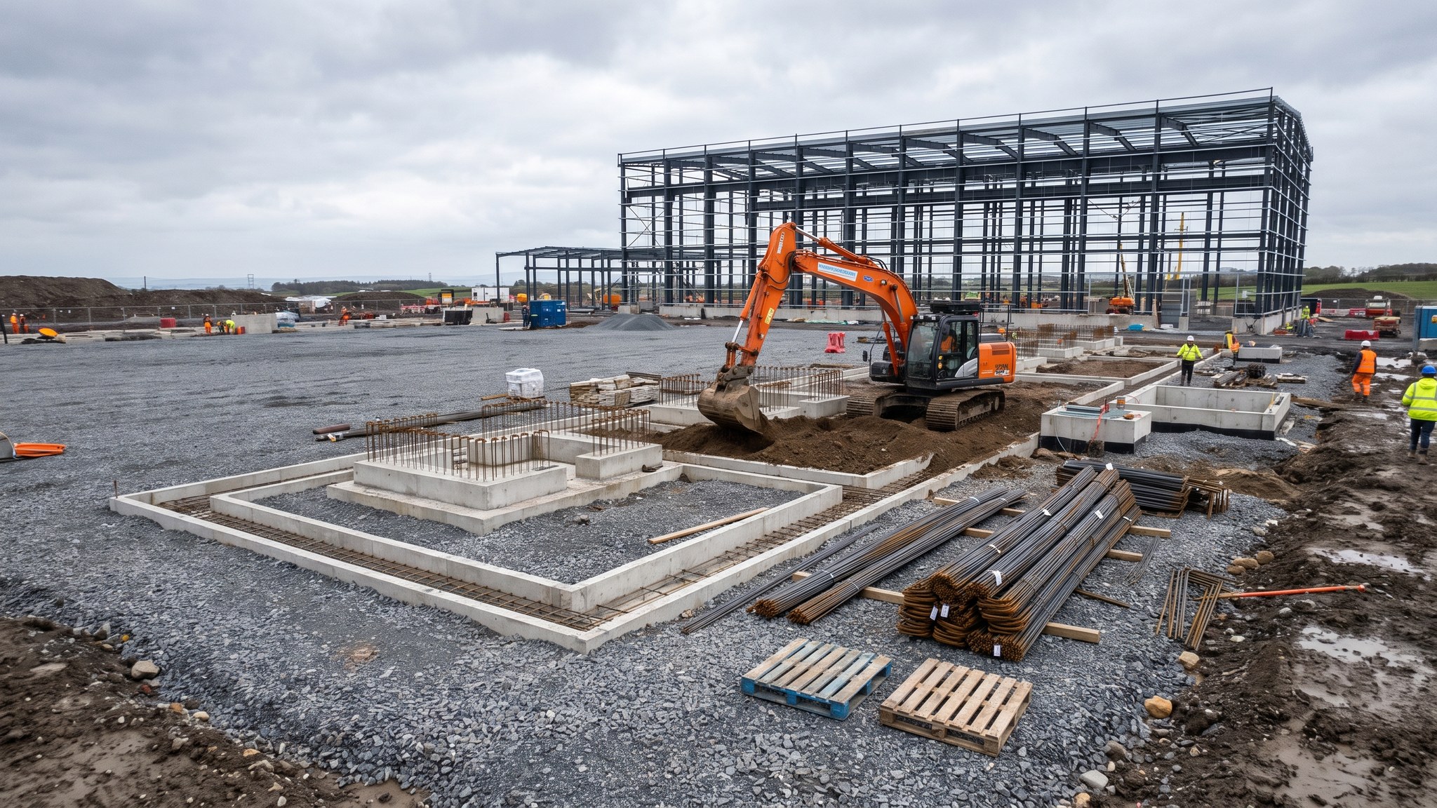
What is Buried services corridors, earthing grid and segregated drainage?
Below the surface of a hydrogen plant runs a dense network that has to be built before the concrete above it. Power cables at several voltages, control and instrumentation, communications, firewater mains, process water, compressed air, nitrogen for utility duties, cooling water, the earthing grid and three or more separate drainage systems all share the same ground. On most projects these are gathered into designed corridors rather than allowed to find their own way, because a plant handling hydrogen cannot be excavated casually once it is operating. Anything that has to be dug up later is dug up in a hazardous area, under permit, quite possibly with the plant shut down.
Separation is the governing idea. The designer sets which services may share a corridor and which may not, how they are separated vertically and horizontally, and how crossings are detailed. Electrical services are separated from one another by voltage and function, and from services carrying liquids. Process pipework is separated from utilities. The reasoning is partly ordinary good practice and partly specific to the hazard: a plant that produces a gas which forms an explosive atmosphere over a very wide range cannot tolerate an arrangement where a fault in one service creates a problem in another, and it cannot tolerate a buried void where a leak could collect. The designer and the technology supplier set the arrangement, and the regulator takes an interest in it.
The earthing grid and the drainage are the two items that most often catch a civils contractor out. The earthing installation is extensive, has to be continuous, has to be tested and has to go in before the slabs are cast - once concrete is over it, a defect is very expensive to reach. Drainage is not one system but several. Clean surface water from uncontaminated areas can generally leave the site through the normal route. Water from process areas is contaminated or potentially contaminated and is collected separately. Firewater has to be captured rather than released. Oily water from the electrical compound is a third stream. Keeping these apart is a design requirement, and on most projects the falls, the sealed sections, the interceptors and the isolation arrangements are all specified rather than left to the drainage contractor.
How does Buried services corridors, earthing grid and segregated drainage work, step by step?
- 1
Step 1: Establish what is already buried
These sites usually have an industrial past and the previous occupier's services are still there. Records are obtained, surveys are run and trial holes are dug to prove position and depth. Abandoned tanks, culverts, ducts and drains are located and dealt with - removed, filled or recorded and left. On most projects this stage produces surprises, and finding them before the excavation programme starts is far cheaper than finding them during it.
- 2
Step 2: Set out corridors from the separation requirements
The designer routes the services into corridors, deciding which may share a trench and which must be kept apart, and how they are separated from one another and from process equipment. Those decisions come from the hazardous-area layout, the electrical design and the process design together, and the designer, the technology supplier and the regulator between them settle the arrangement. The civils package receives the corridor layout as a constraint. Crossings, changes of level and access points are all detailed on the drawings rather than resolved on site.
- 3
Step 3: Install the earthing grid before anything covers it
The earthing installation goes in early and across the whole site. Conductors are laid to the electrical design, connections are made and inspected, electrodes and test points are installed, and the whole installation is recorded before any of it is buried or cast in. On most projects the earthing is tested in sections as it is completed rather than only at the end, because a continuity fault found under a finished slab is a demolition job. The as-built record of the earthing grid is one of the most valuable documents the civils package produces.
- 4
Step 4: Build the drainage as separate systems
Clean surface water, process and potentially contaminated water, and oily water from the electrical compound are built as separate systems with separate outfalls. Sealed sections, interceptors, sumps, isolation valves and firewater retention are installed where the design calls for them. Falls are set out and checked by survey. On most projects a mistaken connection between two systems is treated as a serious non-conformance, because it defeats a control the plant relies on rather than merely creating a maintenance issue.
- 5
Step 5: Avoid buried voids and unventilated chambers
The design deliberately avoids arrangements where gas could accumulate underground. Chambers, ducts and voids in and around the process areas are detailed to the designer's and the technology supplier's requirements, and the civils contractor does not improvise a chamber or a duct entry to suit site convenience. Where sealing is specified between areas, it is built exactly as drawn and inspected before it is covered. This is one of the areas where the reason for a detail may not be obvious to the person building it, so the design intent is normally explained rather than assumed.
- 6
Step 6: Lay ducts, pits and draw points to the cable design
Multi-way duct runs, draw pits, pull points and cable trenches are built to the electrical design, with the pull distances and bend radii the cabling contractor needs. Ducts are proved and sealed as they are completed, and pits are built to the sizes the cable pulling operation requires rather than to a standard product. On most projects the duct network is proved by mandrel and recorded before backfill, because a collapsed or obstructed duct discovered during cable pulling is a programme problem at the worst possible point.
- 7
Step 7: Backfill, compact and record
Trenches are backfilled and compacted to the specification with the correct surround materials, marker tape and any protective covers. Compaction matters because settlement over a service corridor beneath a slab or a road surface reappears later as a defect. Each run is surveyed before backfill so the as-built record shows where things actually are, not where they were drawn. That record is what future maintenance will rely on to avoid excavating blind on an operating plant.
- 8
Step 8: Test, prove and hand over the buried infrastructure
Drainage systems are tested, earthing continuity and resistance results are recorded, ducts are proved and pressure systems are tested to the specification. Results are compiled with the as-built survey and issued as a documented handover. On most projects the buried infrastructure package is handed over as a whole, area by area, before the slabs above it are cast, and any outstanding item is closed before covering rather than carried forward.
What are the benefits of Buried services corridors, earthing grid and segregated drainage?
- Puts the whole below-ground network in before slabs are cast, when it can still be inspected and corrected
- Keeps clean, process and oily water streams apart, so the drainage supports rather than undermines plant safety
- Gives the earthing installation a proper inspection and test regime before it is buried
- Routes services into corridors, greatly reducing the need to excavate on an operating plant
- Produces an as-built record that future maintenance can dig against with confidence
- Allows duct and pit arrangements to be proved before the cabling contractor depends on them
What are the limitations of Buried services corridors, earthing grid and segregated drainage?
- Congested and unforgiving - a service in the wrong corridor may not be correctable once slabs are cast
- Very sensitive to late electrical and process design change
- Extensive excavation on former industrial land brings contamination handling and disposal costs
- Separate drainage systems cost more to build and add operational complexity
- Requires close sequencing with the foundation programme, since everything must be in before the pours
- Settlement over poorly compacted trenches reappears later as a defect in the surface above
What is Buried services corridors, earthing grid and segregated drainage best suited for?
What plant does Buried services corridors, earthing grid and segregated drainage need?
- Excavators with trench support systems and dewatering equipment
- Service location equipment and vacuum excavation for proving existing buried services
- Pipe laying and jointing equipment for multiple drainage and utility systems
- Earthing installation and connection equipment with continuity and resistance test gear
- Duct laying gear, mandrels and duct sealing systems
- Compaction plant suited to trench backfill, with testing equipment
How is Buried services corridors, earthing grid and segregated drainage quality-checked?
- Existing services proven by survey and trial hole before excavation begins
- Separation between services checked against the design before backfill, not after
- Earthing continuity and resistance tested in sections as installed and recorded before covering
- Drainage systems tested and proved separate, with any cross-connection treated as a non-conformance
- Ducts proved by mandrel and sealed, with pit sizes checked against the cable pulling requirement
- Every run surveyed as built before backfill, with trench compaction tested to the specification