Engineered hardstanding, crane pads and skid landing areas
The plant arrives as heavy packaged skids, so the ground the cranes stand on and the ground the skids land on is a designed structure.
Last updated 2026-09-07
What is Engineered hardstanding, crane pads and skid landing areas?
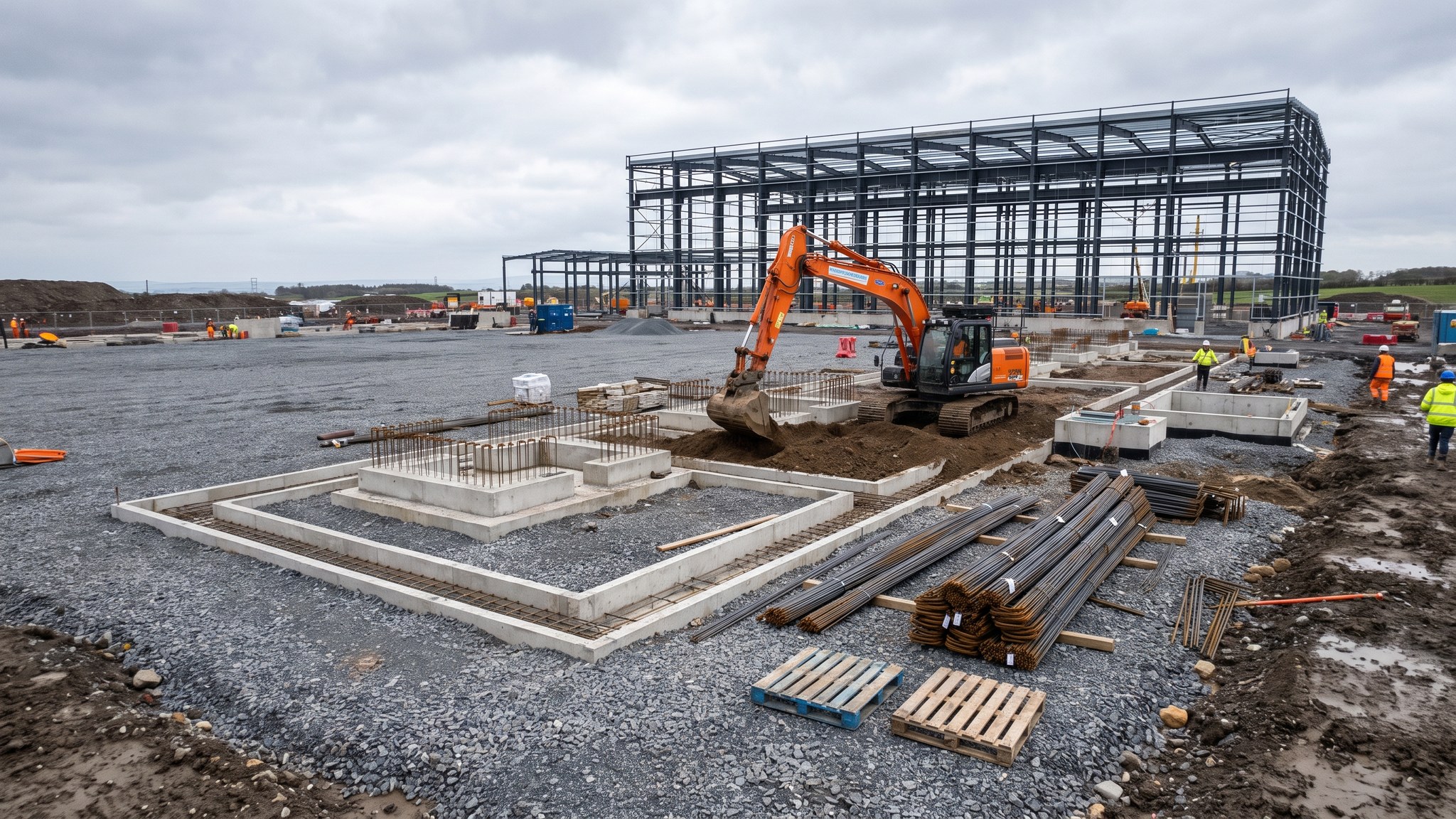
A hydrogen plant is largely assembled rather than built. The process arrives as heavy factory-built skids and containerised packages, the transformers arrive as abnormal loads, and almost everything of consequence is lifted into place by crane. That makes the ground the cranes stand on one of the most important structures on the project, and it is one that is easy to underestimate because when it is right nobody notices it. On most projects the crane pads, the delivery routes, the laydown and the skid landing areas are designed by an engineer against the actual lift plan, not assembled from whatever stone happens to be available.
The loads are severe and concentrated. A large crawler or mobile crane transmits its load through tracks or outriggers into a small area of ground, and the ground on these sites is normally reclaimed or filled. The design has to consider bearing capacity, settlement under sustained load, the effect of the water table, and proximity to excavations, trenches, buried services and the piled foundations already built. On most projects the crane pad design is a documented deliverable signed off before the crane is booked, and it is re-checked whenever the lift plan changes - which it does, because lift plans follow deliveries and deliveries move.
Skid landing areas are a related but separate problem. A packaged unit is landed, jacked, skated or slid into final position, and the surface it moves across has to take those loads without rutting or breaking up. Level tolerance matters because the package has to end up matching a bolt group set to the supplier's drawing. Laydown areas have to be drained, because a package sitting in standing water for weeks before installation is a warranty argument waiting to happen. On many projects the same areas become permanent operational hardstanding once construction ends, so the designer commonly builds them once to the permanent specification rather than twice.
How does Engineered hardstanding, crane pads and skid landing areas work, step by step?
- 1
Step 1: Start from the lift plan and the delivery schedule
The hardstanding design follows the lift plan. The appointed person and the temporary works designer between them establish what is being lifted, from where, by what crane, in what configuration and in what sequence. That determines where crane positions are needed, what loads arrive at the ground and for how long. On most projects the delivery schedule then fixes the order in which the areas are built, because a crane pad needed in the first delivery window has to exist before one needed six months later.
- 2
Step 2: Design the platform against the ground investigation
The temporary works designer takes the ground investigation and designs the platform: thickness, material grading, any geogrid or geotextile reinforcement, and the formation preparation beneath it. Reclaimed and filled ground normally needs more than people expect. Where the water table is high or the fill is variable, the design may include ground improvement or a piled solution beneath the crane position. The output is a drawing and a certificate, not a verbal instruction to the groundworks foreman.
- 3
Step 3: Check proximity to excavations, services and piles
Crane positions on a plant site are rarely in open ground. They sit next to piled foundations, over buried service corridors, alongside open excavations and near drainage runs. The designer sets stand-off distances from open excavations and checks the imposed loads against anything buried. On most projects the buried services are proven by survey and trial holes rather than trusted from a drawing, because these sites frequently contain services left by a previous occupier.
- 4
Step 4: Prepare the formation and build the platform
The formation is stripped, proof-rolled and inspected before any fill is placed. Soft spots are dug out and replaced rather than bridged. Fill is placed in layers, compacted and tested to the specification, with geogrid installed where the design calls for it. The platform is graded to shed water, because a platform that ponds loses strength exactly where the crane needs it. Records of layer thickness, compaction and testing are kept as the platform is built.
- 5
Step 5: Certify the platform and control access to it
The completed platform is inspected against the design and certified in writing before any crane tracks on. The certificate names what it covers and what loads it was designed for. On most projects the platform is then re-inspected at agreed intervals and after any heavy rainfall, and re-certified after repair. Rutting, ponding and edge damage are the early signs that a platform is degrading, and the recorded fatal accidents in this area involve platforms that were adequate on day one and were never looked at again.
- 6
Step 6: Build the skid landing and move-in surfaces
The areas where packaged units are landed and moved into final position are built to a level tolerance as well as a strength requirement, because the package will be skated or jacked across them into a bolt group that cannot move. The surface is designed for the jacking and skating loads, which are concentrated and mobile rather than static. Falls are set so water runs away from the landing position, and the surface is protected from other site traffic once it is complete.
- 7
Step 7: Provide drained laydown for packages awaiting installation
Packages frequently arrive before the foundation that will receive them is ready. Laydown areas are therefore designed for the storage loads, drained so units do not stand in water, and set out so that a package can be picked up and moved without double handling. On most projects the technology supplier states storage and protection requirements for its equipment, and the laydown design has to satisfy them or the supplier's warranty position changes.
- 8
Step 8: Convert construction areas to permanent hardstanding
Once the lifting is finished, many of these areas become permanent operational access, parking and maintenance hardstanding. Where that is known from the outset the designer normally specifies the permanent construction from the start and uses it through the build, which avoids building twice. Surfaces are then repaired where construction has damaged them, final falls and drainage connections are completed, and markings and demarcation are applied to the operational layout.
What are the benefits of Engineered hardstanding, crane pads and skid landing areas?
- Gives cranes a designed and certified surface on ground that is rarely competent naturally
- Reduces the risk of the highest-consequence event on an assembly-led project - a crane overturn
- Delivers the level tolerance that skid landing and move-in operations need
- Keeps expensive packaged equipment out of standing water while it waits for its foundation
- Allows the same structure to serve construction and then permanent operations, avoiding double build
- Provides all-weather access so deliveries with fixed transport windows are not lost to ground conditions
What are the limitations of Engineered hardstanding, crane pads and skid landing areas?
- Consumes a large area of the site and a large volume of imported material
- Has to be redesigned whenever the lift plan or delivery sequence changes, which is often
- Degrades under construction traffic and needs continuing inspection, repair and re-certification
- Constrained by buried services, open excavations and completed piled foundations
- High water tables and variable fill can force ground improvement or piling beneath crane positions
- Drainage from large hardstanding areas has to be managed and, in some areas of the plant, kept separate
What is Engineered hardstanding, crane pads and skid landing areas best suited for?
What plant does Engineered hardstanding, crane pads and skid landing areas need?
- Dozers, graders and rollers for formation preparation and layered fill
- Excavators and dump trucks for dig-out, replacement and material movement
- Compaction testing equipment and proof-rolling plant
- Geogrid and geotextile installation gear where the design calls for reinforcement
- Crawler and mobile cranes, with mats, spreader systems and outrigger pads
- Jacking, skating and skidding equipment for moving landed packages into final position
How is Engineered hardstanding, crane pads and skid landing areas quality-checked?
- Platform design issued as a drawing and certificate before any crane tracks on
- Formation proof-rolled and inspected, with soft spots dug out rather than bridged
- Layer thickness, material grading and compaction testing recorded as the platform is built
- Level tolerance on skid landing areas surveyed against the requirement, not judged by eye
- Routine re-inspection of platforms during the works and after heavy rainfall, with re-certification after repair
- Buried services and completed foundations proved by survey and trial hole before loads are imposed above them