Multi-module topsides and skidded packages
Topsides split into modules for float-over or lifted installation, easing fabrication and vessel constraints at the cost of offshore joining work.
Last updated 2026-09-07
What is Multi-module topsides and skidded packages?
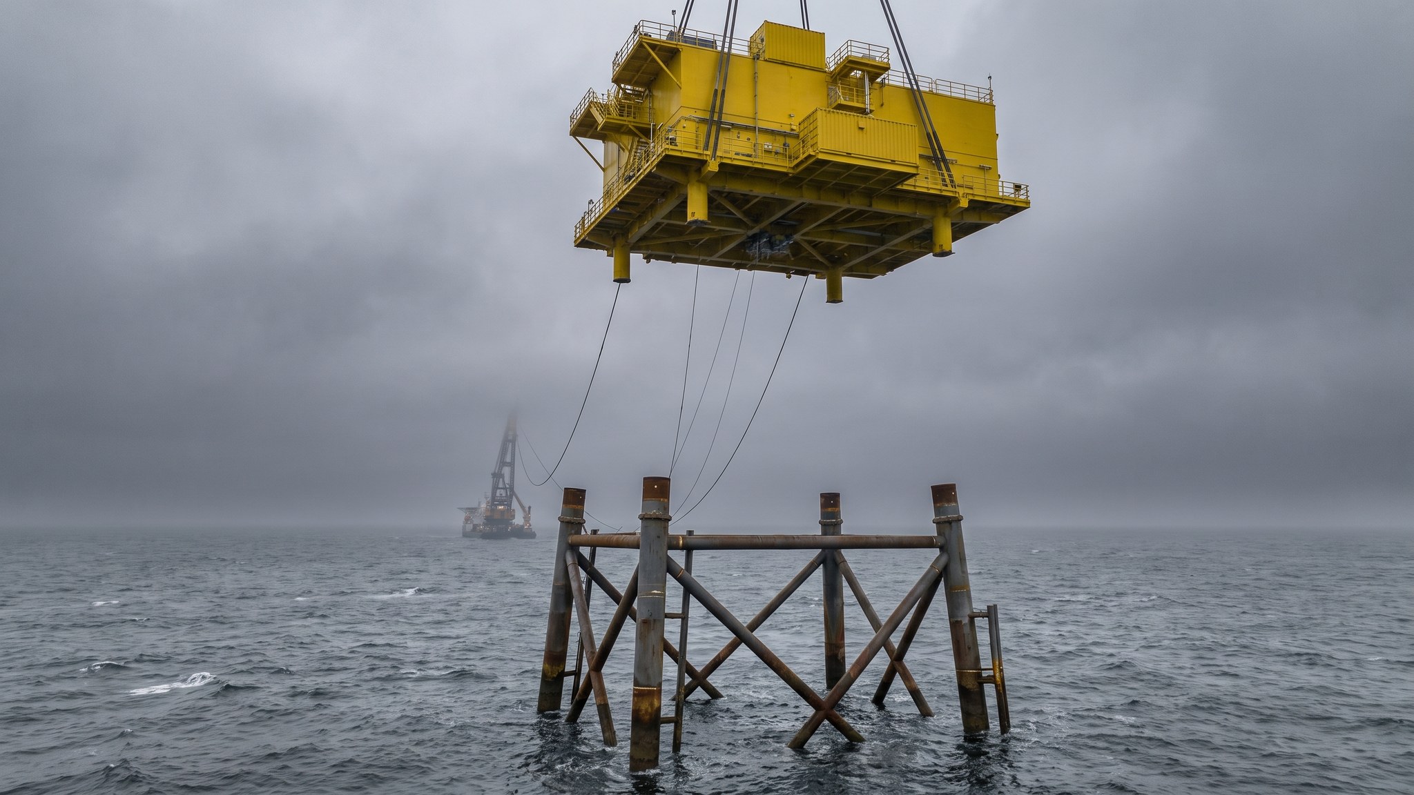
A topside does not have to be installed as one object. Where the complete unit is too heavy for the available vessels, too large for the yard, or simply too big a single point of programme risk, it can be split into modules. Each module is built, fitted out and tested separately, and the modules are then installed one after another and joined together in place. The split is usually along functional lines, so that one module carries a defined set of equipment and its supporting systems, which keeps the connections between modules to a manageable number and lets each module be tested meaningfully on its own.
The attraction is that modularisation loosens almost every constraint that a single large topside imposes. A lighter module can be installed by a smaller and more available vessel. Smaller modules can be built in more yards, including yards that could never take the complete unit, and they can be built in parallel so that the fabrication programme compresses. Load-out, transport and sea fastening all get easier. Skidded packages take the same idea a step further: equipment is built into a self-contained skid, complete with its own frame, its own internal cabling and piping and its own tested systems, and the skid is landed and connected rather than assembled in place.
The cost is joining work offshore. Every split between modules becomes a set of structural connections, cable connections, piping connections and system boundaries that have to be made and tested at sea rather than on land, and that is exactly the work that offshore projects try hardest to avoid. Alignment between modules has to be right, tolerances have to be held across separate fabrications in separate yards, and the testing that would have proved a complete system in the yard now has to be repeated across the joints once the modules are together. The designer decides the split, and the right answer minimises the number and complexity of connections that cross it.
How does Multi-module topsides and skidded packages work, step by step?
- 1
Step 1: Decide the split and where the boundaries fall
The split is an engineering decision made early, and it is driven by weight, by yard capability, by vessel availability and above all by where the fewest connections cross. Boundaries are placed along functional lines so that each module contains a complete set of related equipment and its supporting systems, and so that the interfaces between modules are as few and as simple as possible. A split that cuts through a complex system multiplies offshore work and is avoided even when it looks attractive on weight. The decision is documented with the interface schedule that will govern the rest of the project.
- 2
Step 2: Control the interfaces across separate fabrications
Modules are commonly built in different yards to different programmes, and the only thing keeping them compatible is interface control. A single controlled set of dimensions, tolerances, connection details, cable and pipe schedules and system boundaries is issued to every yard, and changes to it are managed formally. Trial fitting of connection details, dimensional control surveys during fabrication and a common survey datum are all used to make sure the modules will actually go together. This work is unglamorous and it is what determines whether the offshore joining is straightforward or painful.
- 3
Step 3: Build and test each module complete
Each module is fitted out and tested as far as it can be on its own, with its internal cabling installed and terminated, its systems commissioned to the module boundary and its records assembled. The aim is that each module arrives offshore proven up to its interfaces, so the only testing left is across the joints. Skidded packages are the extreme version of this: a complete assembly on its own frame, factory tested and shipped ready to be landed and connected. The more that is closed out at this stage the less exposure there is offshore.
- 4
Step 4: Weigh, load out and transport module by module
Each module is weighed and its centre of gravity established before load-out, because each is a separate lift with its own plan. Load-out, sea fastening and transport are arranged per module, and modules may travel separately or together depending on the barge and the programme. Protection for the transit is fitted at every open interface so that connection faces arrive clean and undamaged. Sequencing matters here: the modules have to arrive in the order they will be installed, which constrains the fabrication programme as well as the shipping.
- 5
Step 5: Install the substructure and the first module
The substructure is installed, piled, levelled and surveyed, and the survey is issued before the first module sails. The first module is landed and secured, and it becomes the datum for everything that follows, so its position and level are surveyed carefully once it is down. Any deviation is measured and its consequences for the next module are worked out before that module arrives. Getting the first module right is worth a great deal of care, because every subsequent alignment problem compounds from it.
- 6
Step 6: Land and align the remaining modules
Each further module is lifted or skidded into place against the one already installed, guided by mating arrangements designed for the purpose, and aligned before it is secured. Skidded packages are landed and pushed into position on rails or skid beams, which is a controlled and repeatable way of moving a heavy package into a tight space. Alignment is checked by survey rather than by eye. Once a module is aligned and secured the structural connections across the joint are made permanent to the procedure the designer has set.
- 7
Step 7: Make and test the connections across the joints
The connections that cross each boundary are made in turn: structural, cable, piping, cooling, control and safety systems. Each is made to a controlled procedure with its own records, and each is tested once made. This is the work that modularisation created and it is the part of the campaign most exposed to weather and to access constraints, so it is planned in detail and resourced properly. The interface schedule prepared at the start of the project is the checklist used to prove that nothing has been missed.
- 8
Step 8: Retest the systems end to end and hand over
Once the joints are complete, systems that were only proved to a module boundary in the yard are tested end to end across the assembled platform. That retesting is a real scope of work and it is planned as such, using the module records as the baseline so that only what changed is repeated. The cables are pulled in and terminated and the platform is handed to the commissioning team. Energisation itself is a controlled step carried out with the network operator under a formal authorisation regime.
What are the benefits of Multi-module topsides and skidded packages?
- Brings very large topsides within reach of smaller, cheaper and more available installation vessels
- Modules can be built in more yards and in parallel, compressing the fabrication programme
- Load-out, sea fastening and transport are all easier for a module than for a complete topside
- Skidded packages arrive factory tested and are landed and connected rather than assembled in place
- Spreads programme risk across several fabrications rather than concentrating it in one
- A late or damaged module does not necessarily stop the whole installation
What are the limitations of Multi-module topsides and skidded packages?
- Creates structural, cable, piping and system connections that must be made and tested offshore
- Interface control across separate yards is demanding and failures show up at the worst possible moment
- Systems proved only to a module boundary have to be retested end to end once assembled
- Alignment tolerances have to be held across independent fabrications and independent surveys
- Several installation operations instead of one, each needing its own weather window
- Module sequencing constrains both the fabrication programme and the shipping arrangements
What is Multi-module topsides and skidded packages best suited for?
What plant does Multi-module topsides and skidded packages need?
- Two or more fabrication yards with load-out capability for the individual modules
- Transport barges and tugs, with sea fastening and interface protection for each module
- Installation vessel sized for the heaviest single module rather than the complete topside
- Skidding equipment, skid beams, rails and pushing or pulling gear for skidded packages
- Mating and alignment arrangements, guides and temporary support steelwork at each joint
- Survey spread for dimensional control in the yards and for alignment offshore
How is Multi-module topsides and skidded packages quality-checked?
- Interface schedule and controlled dimensional set issued to every yard, with changes formally managed
- Dimensional control surveys during fabrication against a common datum, with trial fitting of critical details
- Each module weighed and tested to its boundary before load-out, with records carried forward
- First module position and level surveyed after landing and used as the datum for the remainder
- Alignment at each joint verified by survey before the structural connections are made permanent
- Every connection across a boundary recorded and tested, with end to end system retesting closed out against the interface schedule