Export cables
The large cables that carry the whole output to shore, very long, made in limited lengths so joints matter, and the single largest point of failure risk on the project.
Last updated 2026-09-07
What is Export cables?
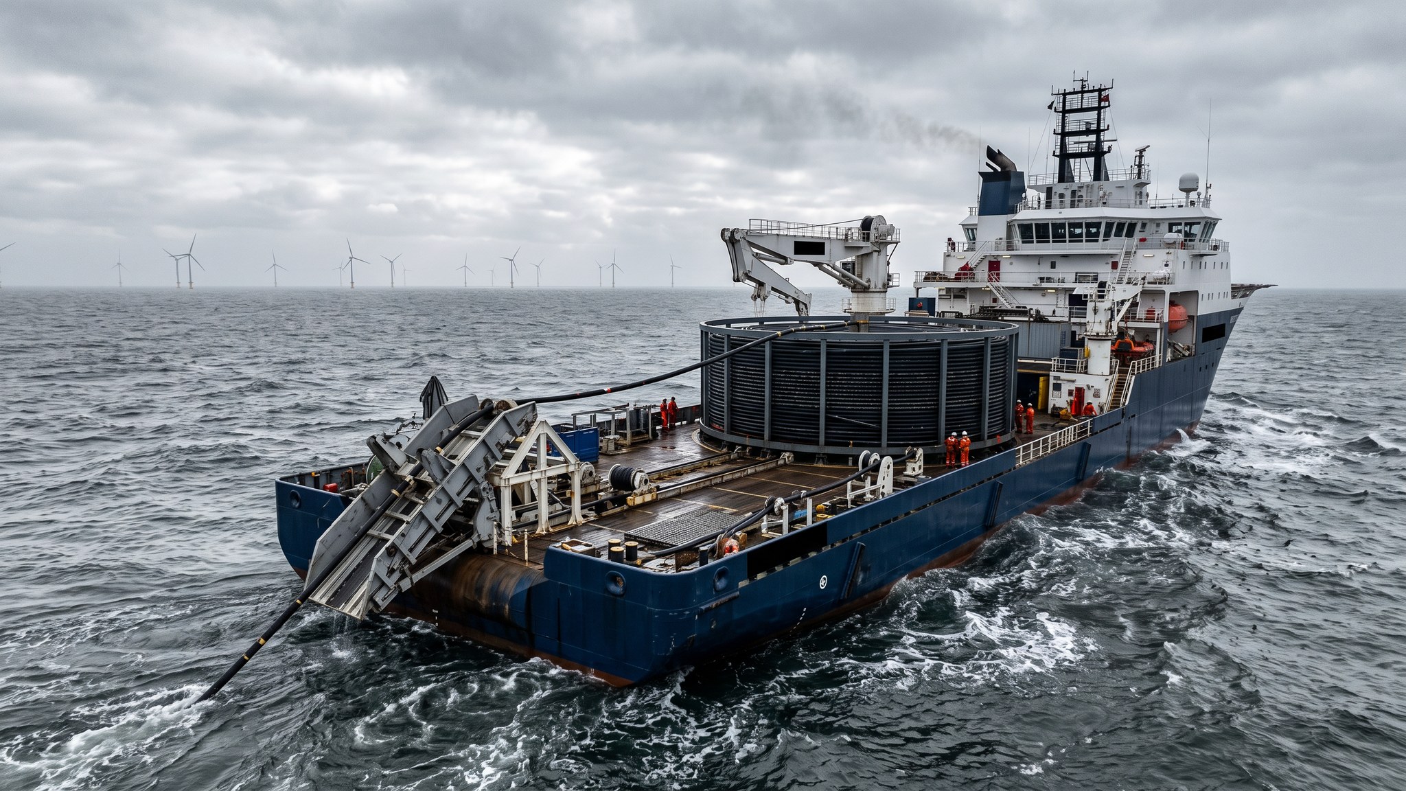
The export cable is the route the entire output of the wind farm takes to reach land. Where an array cable carries one string, the export cable carries everything, and that changes its character completely. It is physically much larger, much heavier per metre and far more expensive, and its route can be tens of kilometres long or considerably more. Most projects install more than one export cable, partly because a single cable would be too large to make and handle and partly because putting the whole project output through one asset is a risk few developers will accept. Even so, losing one export cable takes a large share of the revenue off the network until it is repaired, and repairs offshore are measured in months.
Length is the governing practical constraint. Cable of this size can only be made in limited continuous runs and only carried in limited quantities on any one vessel, so a long export route has to be installed as a series of lengths joined together. Every joint is a point where the cable was cut and remade, and joints are made either in the factory before the cable ever leaves, or offshore on the deck of a vessel when a route cannot be covered otherwise. Factory joints are made in a clean controlled environment and are treated as part of the cable. Offshore joints are made in a temporary habitat on a moving deck and are avoided wherever the programme allows, because they are slow, they occupy the vessel, and they are difficult to complete inside a workable weather window.
Export cable is therefore the single largest concentration of risk on an offshore wind construction project. The manufacturing slot is booked years ahead and is difficult to replace if it is missed. The installation needs the largest lay vessels, which are scarce. The route crosses other assets, fishing grounds, shipping lanes and eventually a consented landfall, and any one of those interfaces can stop the campaign. Once installed, the cable is vulnerable to anchors, fishing gear and seabed movement for its whole life, and industry experience is that most offshore wind insurance losses relate to cables rather than to turbines. Almost every decision the designer takes about burial, protection and route selection is made with that record in mind.
How does Export cables work, step by step?
- 1
Step 1: Select and consent the route corridor
Route selection starts wide and narrows down. A corridor is chosen between the offshore substation and the landfall that avoids the worst ground, keeps crossings of other cables and pipelines to a minimum, respects shipping and anchorage areas, stays clear of protected seabed habitat where it can and reaches a landfall that can actually be consented. Survey work then runs along that corridor to build a detailed picture of the seabed and the shallow geology. The corridor is consented as part of the project, and the final route within it is fixed by the designer against the survey. Changing the corridor later is a consenting exercise, not an engineering one.
- 2
Step 2: Agree the crossings and the third party interfaces
Any existing cable or pipeline on the route has to be crossed, and each crossing is agreed individually with whoever owns the asset being crossed. The agreement covers how the crossing will be built, what separation and protection will be provided, who inspects it and who is responsible for it afterwards. Crossings are physically built by placing protection over the existing asset, laying the export cable over the top and then protecting it in turn, so each one is a small marine construction project in its own right. These agreements take a long time and are a common cause of delay, so they are started early and tracked as a programme item rather than a technical detail.
- 3
Step 3: Manufacture in lengths and plan the joints
The route length is divided into manufactured lengths that the factory can produce continuously and the vessel can carry. The designer and the installation contractor together decide where the joints fall, aiming to put them in ground that is easy to work in, away from crossings and away from the busiest water. Where the route can be covered by factory-jointed lengths that is always preferred, because the joint is then made in the factory and tested with the rest of the cable. Where it cannot, an offshore joint is planned into the campaign with its own vessel time, its own habitat and its own weather allowance.
- 4
Step 4: Load out and mobilise the lay spread
Loading an export cable onto a lay vessel takes days rather than hours, and it is done at a quay with the depth and the load capacity to take a fully loaded vessel of that size. The cable is coiled into the carousel under controlled tension and the loading is monitored throughout, because damage inflicted during loading will not be discovered until much later. Accessories, joint equipment, protection materials and the burial spread are mobilised alongside. Vessel availability for cable of this size is limited, and a missed slot can push a project into the following season.
- 5
Step 5: Pull in the offshore end and start the lay
The campaign usually starts at the offshore substation, where the cable end is pulled up into the structure in the same way as an array cable but with larger equipment and a much heavier cable. The end is secured and left ready for termination. The vessel then lays away from the platform along the surveyed route, holding station and controlling tension continuously, with the cable monitored where it meets the seabed. Lay progress is slow and deliberate, and the vessel works around traffic, guard vessels and any activity in the area.
- 6
Step 6: Make the crossings and any offshore joint
At each crossing the vessel works to the agreed method, laying over the pre-placed protection and then having the crossing protected once the cable is down. If an offshore joint is needed, both cable ends are recovered to the deck, a temporary habitat is set up over the working area and the joint is made by a specialist crew. The joint then has to go back over the side and onto the seabed in a controlled way without damaging it. Weather governs the whole operation, and the vessel commonly waits for a suitable window rather than starting and being caught out.
- 7
Step 7: Bury the cable and protect what cannot be buried
Burial follows the lay, using a trenching spread suited to the ground along the route. The route is worked in sections and the achieved burial is recorded continuously against the position. Ground that will not accept the tool, existing infrastructure and crossings all leave lengths that cannot be buried, and those are protected by other means instead. The project keeps a live picture of which lengths are buried, which are protected and which remain outstanding, because that picture is what the network operator and the insurers will want to see.
- 8
Step 8: Terminate at both ends, test and record
The offshore end is terminated inside the substation and the onshore end is terminated at the transition joint bay at the landfall, connecting the marine cable to the land cable that runs on to the onshore substation. Both terminations are made by specialist crews to a controlled procedure. The complete cable is then tested end to end before it is ever taken live, and the results are compared against the factory records. The as-laid route, the burial and protection records, the crossing records, the joint records and the test results form the cable file, and that file is the reference for every future inspection, repair and insurance discussion.
What are the benefits of Export cables?
- Carries the entire project output on a small number of assets, keeping the offshore infrastructure simple
- Factory jointed lengths allow long routes to be covered without cutting and remaking cable offshore
- Installing more than one cable gives partial output if one is lost, rather than a total outage
- A single well surveyed corridor covers all the export cables, sharing survey and consent effort
- Once buried and protected, the cable is a passive asset with no moving parts and very low running cost
- The route and the crossings are agreed and documented once, giving a clear basis for the whole life of the asset
What are the limitations of Export cables?
- The single largest concentration of failure risk on the project, and the dominant source of industry loss experience
- Manufacturing slots are booked years ahead and are extremely difficult to replace if missed
- Requires the largest and scarcest lay vessels, so vessel availability drives the programme
- Offshore joints are slow, weather sensitive and best avoided, but a long route may leave no alternative
- Crossing agreements with third parties are slow to negotiate and sit outside the project team's control
- Repair offshore is measured in months, with lost output for the whole period
What is Export cables best suited for?
What plant does Export cables need?
- Large cable lay vessel with high carousel capacity, tensioners and dynamic positioning
- Trenching spread capable of working in the ground types found along the route
- Jointing habitat and specialist jointing crews where an offshore joint is planned
- Rock placement or protection vessel for crossings and for lengths that cannot be buried
- Guard vessels and traffic management for the duration of the campaign
- Survey spread for route survey, as-laid recording, burial verification and crossing inspection
How is Export cables quality-checked?
- Factory testing of every manufactured length, including the factory joints, held as the baseline record
- Loading monitored and recorded, with tension and coiling controlled to prevent damage before the cable sails
- Continuous position and touchdown monitoring during lay, checked against the consented route corridor
- Burial and protection recorded continuously along the route, with a register of every unburied length
- Crossing construction inspected and signed off against the agreement with the asset owner
- End to end testing before the cable is taken forward, reconciled against the factory baseline and filed with the as-built records