Single-blade installation
Each blade lifted and bolted on individually - the most lifts, but the smallest and most weather-tolerant ones.
Last updated 2026-09-07
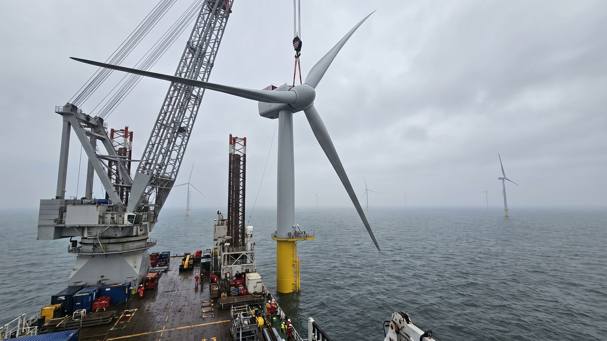
What is Single-blade installation?
Single-blade installation builds the rotor in the air. The tower sections go up, the nacelle is landed on the tower, the hub is fitted, and then each blade is lifted individually from the deck and bolted to the hub, with the hub rotated between blades to present the next flange. Nothing is pre-assembled, which means more separate operations offshore than any other method, but every one of those operations is smaller. That is the trade the whole method rests on, and it is why single-blade installation has become the default for the largest machines.
The reason smaller lifts matter is wind. A blade is a very large aerofoil, and the load the wind puts on it while it hangs from a crane rises steeply with wind speed. A complete rotor presents far more area than a single blade, so the wind speed at which the operation has to stop is lower for a pre-assembled rotor than for a blade on its own. Working blade by blade therefore raises the wind speed at which the crew can keep going, and on an exposed site through a long campaign that difference converts directly into more working days. The equipment reflects it: modern blade installation uses a yoke or gripper tool that holds the blade under control rather than letting it swing on slings, often with active motion compensation, and that tool is a large part of why the method works at all.
What it costs is time and complexity per turbine. Three separate blade lifts, each with its own approach, alignment and bolting sequence, take longer in total than one rotor lift, and each one needs the hub aligned, locked and rotated between blades. Alignment at height is the difficult part: the blade root flange has to be brought to the hub flange precisely, with a large flexible object being manoeuvred by a crane. Crews get very good at it, and on a settled campaign a complete turbine can be installed within a day or two, but the method rewards experience and punishes an inexperienced spread. As with every offshore lift, the sequence is planned by the installation contractor against defined weather limits and independently reviewed before the campaign starts.
How does Single-blade installation work, step by step?
- 1
Step 1: Load out components and plan the sequence
Tower sections, nacelle, hub and blades are loaded at the marshalling port onto the installation vessel or its feeders, in the order the offshore sequence needs them, and sea-fastened. Blades are the awkward item: they are long, light for their size and easily damaged, and they travel in racks designed for the purpose. How many complete turbine sets fit on the deck sets how many positions the vessel covers before returning to port, and that round trip is one of the biggest levers on campaign duration.
- 2
Step 2: Position the vessel and prepare the foundation interface
The vessel arrives at the foundation, jacks up or holds station, and the crew access the structure to prepare the tower flange. Bolts, shims and the tower base interface are checked against the as-built record handed over by the foundation contractor. The crane is configured and the lift plan for the position is confirmed, including the weather limits for each stage. Lifts of this scale are planned by the installation contractor and independently reviewed before work begins.
- 3
Step 3: Erect the tower
Tower sections are lifted and set in sequence, bolted at each flange and the bolts tightened in a controlled pattern to the values the specification gives. Internal fit-out - ladders, lift, platforms, cabling - is largely pre-installed in the sections, and the connections between sections are made up as the tower rises. Verticality and flange condition are checked as each section lands, because errors compound upwards and the nacelle interface at the top has very little tolerance.
- 4
Step 4: Land the nacelle
The nacelle is the heaviest single component and its lift is the one that sets the crane requirement for the whole project. It is lifted from the deck, brought over the tower top and landed on the yaw interface under close control, using taglines or a dedicated lifting frame to manage rotation. Once bolted down and torqued, the nacelle gives the crew a working platform at height and the electrical and control connections between tower and nacelle are made up.
- 5
Step 5: Fit the hub and prepare for the first blade
The hub is lifted and fitted to the main shaft, or arrives already attached to the nacelle depending on the machine, and the rotor lock and turning gear are proved. The hub is then rotated so that the first blade flange presents at the angle the procedure requires, and locked in that position. Access into the hub is established so that technicians can work the bolts from inside. The blade installation tool is rigged and function-tested before any blade leaves the deck.
- 6
Step 6: Lift and bolt the first blade
The blade is picked up from its rack in the gripper or yoke tool, lifted clear and brought up to the hub. The tool holds the blade at a controlled attitude rather than letting it hang free, and where fitted the motion compensation keeps the root steady against the hub. The root flange is aligned to the hub flange, the studs are engaged and the bolts are made up and tightened in the pattern and to the values the specification requires. The tool is released only when the connection is complete and confirmed.
- 7
Step 7: Rotate and repeat for the remaining blades
The rotor is turned to bring the next flange into position and locked again, and the sequence repeats. Between blades the crew monitor the weather against the limits for the next lift, because a partially bladed rotor is an unbalanced structure and the procedure defines what state it may be left in. Each blade is inspected for transit and handling damage before it goes up, since a blade with a damaged leading edge is far cheaper to reject on the deck than to change out later.
- 8
Step 8: Complete, commission and hand over
With the rotor complete, the bolted connections are verified and recorded, the rotor lock is released and the machine is checked through its initial functional tests. Cable pull-in and termination, control system commissioning and grid energisation follow, sometimes in the same visit and often in a later campaign. The installation records - torque records, alignment checks, damage inspections and the lift logs - are assembled into the turbine file for that position and handed to the operator.
What are the benefits of Single-blade installation?
- The most weather-tolerant method, because each individual lift presents the least area to the wind
- Highest number of workable days over a long campaign on an exposed site
- Handles the largest blades, where a pre-assembled rotor would exceed what any vessel could lift or carry
- Component packing on deck is efficient, since blades stack in racks rather than travelling as an assembled rotor
- No onshore pre-assembly area needed at the marshalling port beyond ordinary component storage
- A damaged blade can be swapped out on the deck without disturbing an assembled rotor
What are the limitations of Single-blade installation?
- The greatest number of separate offshore operations, so the most time per turbine in good weather
- Alignment of a large flexible blade to the hub at height is demanding and rewards an experienced crew
- Needs a specialist blade gripper or yoke tool, and its availability and reliability become critical path
- The rotor has to be turned and locked between blades, adding steps and hold points
- A partly bladed rotor is an unbalanced state that constrains what the crew can leave overnight
- More work carried out at height offshore than any alternative method
What is Single-blade installation best suited for?
What plant does Single-blade installation need?
- Jack-up or floating installation vessel with a crane sized for the nacelle lift and hook height for the hub
- Blade gripper or yoke installation tool, with motion compensation where fitted
- Blade transport and storage racks with sea fastening
- Bolt tensioning and torquing equipment for tower, nacelle and blade root connections
- Rotor lock, turning gear and hub access arrangements
- Feeder barges and tugs where components are shuttled from the marshalling port
How is Single-blade installation quality-checked?
- Component inspection on deck before every lift, particularly blade leading and trailing edges
- Tower flange bolt tightening records for every connection, with the tightening pattern followed and logged
- Verticality checks as each tower section lands, recorded against the specification tolerance
- Blade root bolt tensioning records for each blade, with the tool calibration certificates on file
- Lift plans and weather limit records retained for each position as evidence the procedure was followed
- Post-installation functional checks and the complete turbine file handed to the operator
More turbine installation methods
Next method
Pre-assembled rotor