Gantry (Cartesian) printing
A frame spanning the work moves a nozzle in three axes, laying a cementitious material in layers within a bounded footprint.
Last updated 2026-09-05
What is Gantry (Cartesian) printing?
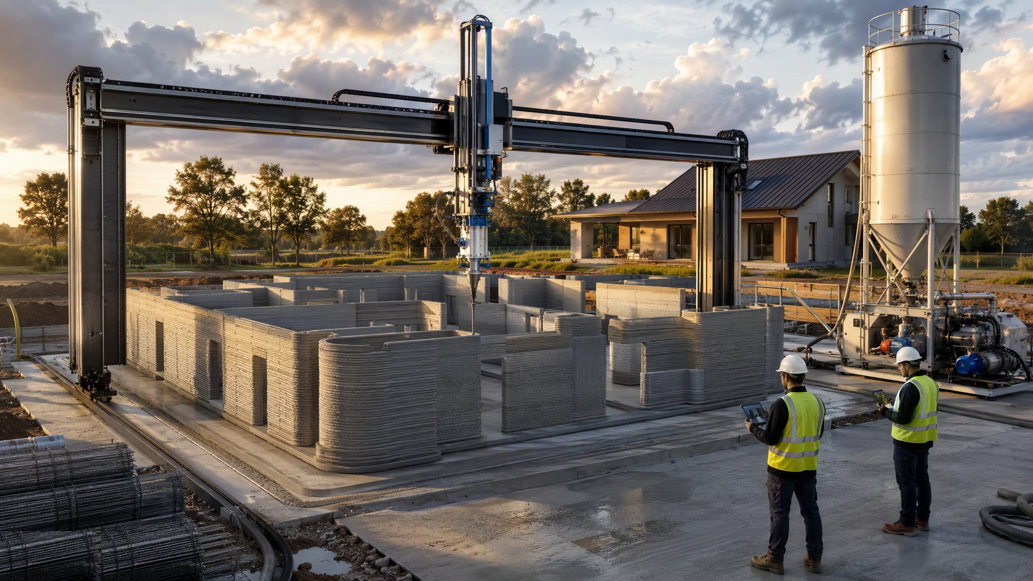
Gantry printing is the most familiar form of additive construction. A rigid frame is erected over the area to be printed, and a print head travels along it in three axes - along, across and up - extruding a cementitious material in continuous layers that build the wall from the ground upwards. The geometry of the machine is simple and rigid, which is its main advantage: motion is predictable, the printable volume is defined by the frame, and positional accuracy is easier to hold than on a machine with more freedom. The material is mixed and pumped continuously to the nozzle, and the printed profile is typically a hollow or ribbed wall form rather than a solid section.
What the frame gives in accuracy it takes in reach. The printable volume is exactly the volume inside the gantry and no more, so the building - or the part of it being printed - has to fit within a bounded footprint decided before the frame goes up. Printing a larger building means erecting a larger gantry, or repositioning the frame and printing in sections, and repositioning is a slow and carefully surveyed operation rather than a matter of moving a machine along. The gantry itself has to be founded, levelled and squared, and it needs to be stiff enough that the print head does not wander under its own motion or in wind, which is why gantry printing is usually enclosed or at least sheltered on anything but the calmest sites.
Additive construction of this kind remains an emerging method rather than an established one. The approvals route is still developing, the durability record is short by construction standards, and there is no long-standing body of accumulated practice of the sort that sits behind masonry or in-situ concrete. In practice this means the engineer designs the element and the approving authority accepts it case by case, usually supported by testing on the specific material and the specific printed geometry rather than by reference to established values. The printable material itself is a specialist product with demanding requirements - it must pump, extrude cleanly and then stiffen quickly enough to carry the layers above without slumping - and its composition is a matter for the material supplier and the designer. Projects that have gone well have generally been those that treated the printing as one part of a conventional structural design rather than as a replacement for it.
How does Gantry (Cartesian) printing work, step by step?
- 1
Step 1: Establish the design and the approvals route early
Because the method is emerging, the structural design basis and the route to approval are settled before anything else. The engineer determines how the element carries load, what the printed material contributes, where conventional reinforcement or in-situ concrete is required, and what testing is needed to support the design. The approving authority is engaged early, because it will accept the proposal case by case rather than against a settled precedent. On most projects this conversation, not the printing, is the long lead item.
- 2
Step 2: Prepare the base and set out
Printing starts from a prepared, level and accurately set-out base - typically a conventional slab or foundation with starter reinforcement and service provisions already in place, because they are extremely difficult to introduce afterwards. The setting out has to be right to the accuracy the machine works to, and the interface between the printed wall and the base is a designed detail rather than simply the point where printing begins.
- 3
Step 3: Erect, level and calibrate the gantry
The frame is erected over the print area, founded and levelled, and squared and calibrated so that the machine's coordinate system matches the site setting out. The frame must be stiff enough to hold position while the head accelerates and decelerates, and its footings must not settle differentially during the print. Calibration is checked before each print run, and the printable volume is confirmed against the geometry to be printed.
- 4
Step 4: Set up material mixing and delivery
A continuous supply of printable material is established - batching or mixing plant, pump and delivery line to the print head. The material must be consistent from batch to batch, because a change in its behaviour shows up immediately as a change in the printed bead. Its composition, mix proportions and admixtures are specified by the material supplier and the designer for the conditions on the day, and the line and head are set up and purged before the print begins.
- 5
Step 5: Print a test wall and tune the parameters
Before production printing, a test element is printed to prove the whole system together: nozzle travel speed, extrusion rate, layer height and width, and the time between layers. These parameters interact - print too fast and layers do not bond, print too slow and the material stiffens before the next layer arrives, print too high a wall too quickly and the lower layers deform under the weight above. The parameters are tuned on the test element and recorded, and specimens are taken for testing.
- 6
Step 6: Print the element in continuous layers
The head follows the programmed path, extruding a continuous bead that forms the wall profile - commonly a twin or ribbed hollow section rather than a solid wall. Layers are laid at a rate that keeps the interface between them fresh enough to bond while the wall below is stiff enough to carry the load. Printing is monitored continuously, and stoppages matter: a paused print leaves a cold joint whose treatment is decided by the designer, not by the operator. Temperature, humidity and wind all change how the material behaves, which is why sheltering the operation is usual.
- 7
Step 7: Form openings, build in fixings and complete the structure
Openings, lintels, service routes, fixings and connections to floors and roof are formed as printing proceeds, using inserts, formers or temporary support as the design requires. Reinforcement and in-situ concrete are placed where the engineer has specified them - on most printed buildings the structural capacity comes from these elements rather than from the printed material alone. Floors, roof and the remaining structure are then built conventionally.
- 8
Step 8: Cure, inspect and finish
The printed element is cured as the material supplier requires, protected from rapid drying, and inspected for layer bonding, verticality, dimensional accuracy and any cracking or deformation. Test specimens are assessed against the design assumptions. The printed surface is a ribbed, layered finish, and whether it is left exposed, rendered, coated or clad is a design decision made in advance, since the surface is very hard to change afterwards.
What are the benefits of Gantry (Cartesian) printing?
- Rigid, simple machine geometry makes motion predictable and positional accuracy easier to hold
- The printable volume is clearly bounded and easy to plan around
- Curved and non-repeating wall geometry costs little more than straight, since there is no formwork to make
- Removes the formwork package for the printed elements, with its labour, material and waste
- Small crew for the printing operation itself compared with traditional walling
- Openings, service routes and fixings can be formed as printing proceeds rather than cut afterwards
What are the limitations of Gantry (Cartesian) printing?
- The frame limits the building - printing beyond it means a bigger gantry or a slow, surveyed repositioning
- Erecting, founding, levelling and calibrating the gantry is a significant operation before any printing starts
- Highly sensitive to weather, so the operation is usually sheltered or enclosed
- An emerging method - the approvals route, the durability record and the design basis are still developing
- Structural capacity generally comes from reinforcement and in-situ concrete, not from the printed material alone
- A stoppage mid-print leaves a cold joint that has to be assessed by the designer
- Specialist material, plant and operators, with a supply chain that is still thin
What is Gantry (Cartesian) printing best suited for?
What plant does Gantry (Cartesian) printing need?
- Gantry frame with three-axis drive system, founded and levelled over the print area
- Print head with nozzle, extrusion control and its delivery line
- Batching or mixing plant with continuous output and consistent control of the mix
- Progressive cavity or similar pump matched to the material and the delivery distance
- Control system with the print path programmed from the model
- Weather enclosure, sheeting or shelter over the print area
- Survey equipment for calibrating the frame and checking the printed geometry
- Conventional plant for foundations, reinforcement, in-situ concrete and the remaining structure
How is Gantry (Cartesian) printing quality-checked?
- Structural design basis and the approvals route agreed with the engineer and the approving authority before work starts
- Gantry founded, levelled, squared and calibrated to the site setting out, and re-checked before each print run
- Test element printed and print parameters - speed, extrusion rate, layer height, layer interval - recorded
- Material consistency checked batch to batch, with specimens taken for testing against the design assumptions
- Continuous monitoring of the print, with stoppages and cold joints logged and referred to the designer
- Dimensional and verticality survey of printed elements against the model
- Inspection of layer bonding, deformation and cracking, and of reinforcement and in-situ elements before they are enclosed
- Curing and protection carried out to the material supplier's requirements and recorded
More 3d printing and additive construction methods
Next method
Robotic arm printing