Robotic arm printing
An articulated arm on a fixed or mobile base prints with far more freedom than a gantry - and turns reach into a workflow problem.
Last updated 2026-09-05
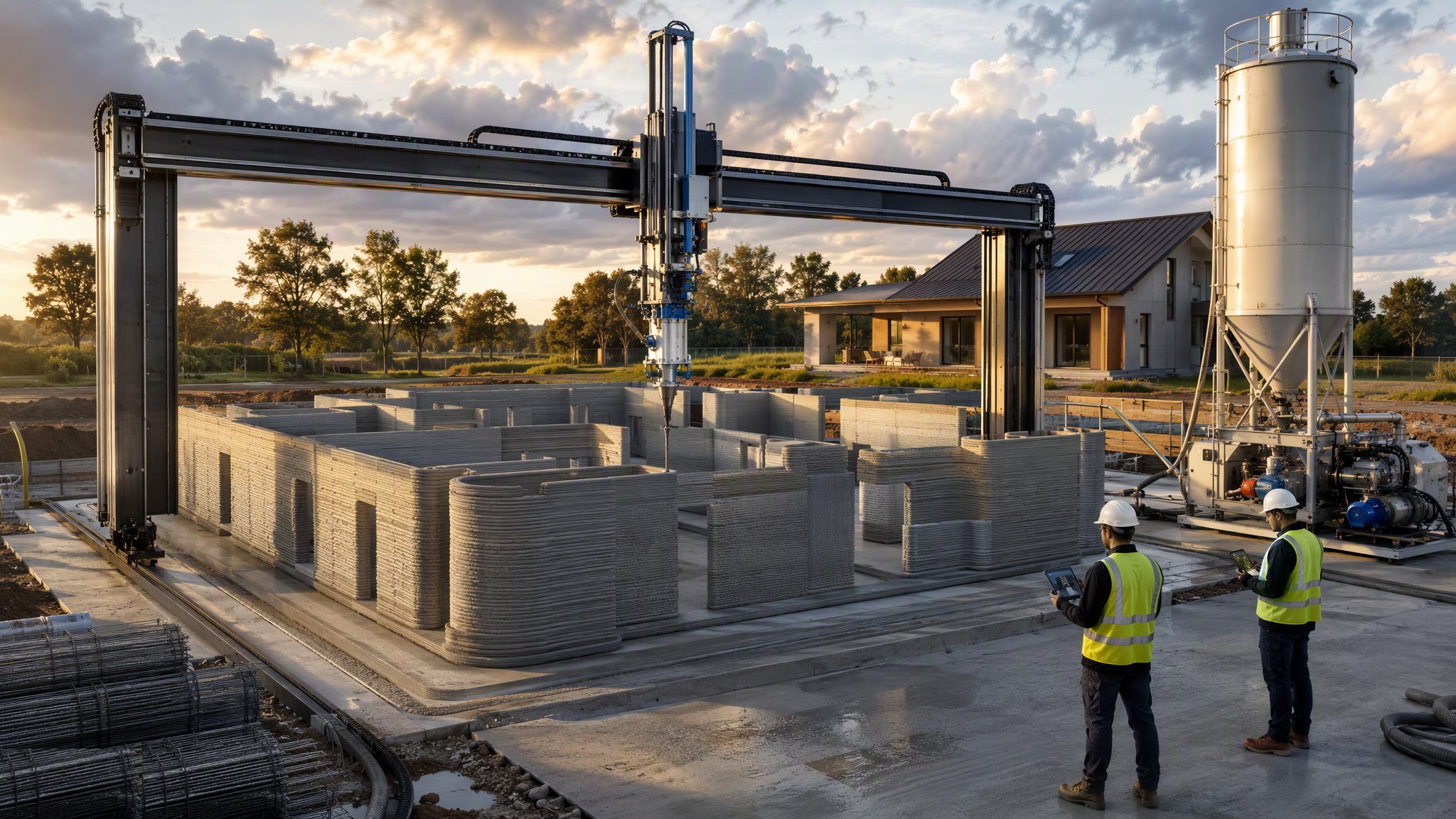
What is Robotic arm printing?
Robotic arm printing replaces the rigid frame with an articulated arm, usually mounted on a fixed pedestal, a tracked or wheeled base, or a crawler that can move around the work. The arm carries the print head and can orientate it in ways a three-axis gantry cannot, which allows overhangs, corbelled and inclined surfaces, varying nozzle angles and printed geometry that a purely vertical layer stack cannot produce. It is also a far less bulky piece of plant than a gantry spanning a whole building, and it can be brought to the work rather than the work being brought inside a frame.
The freedom comes with a different constraint. An arm has a working envelope shaped like part of a sphere around its base, and everything it prints has to be within that reach. On anything larger than a small element, the arm therefore has to be repositioned, and repositioning is the central workflow issue of the method. Each new position must be surveyed and the machine re-registered to the building's coordinate system, because the arm has to know precisely where it now stands in relation to what it has already printed. Any error in that registration shows up as a step or a misalignment at the junction between print zones. Projects that use arm printing successfully tend to plan the print zones and the machine positions as carefully as the geometry itself, and to design the junctions between zones as deliberate joints rather than hoping they will be invisible.
Like all additive construction, this is an emerging method. The approvals route, the durability record and the structural design basis are still developing, and the engineer designs the element while the approving authority accepts it case by case, usually with testing on the specific material and geometry. Arm printing carries an additional consideration: because the arm can print inclined and overhanging geometry, the buildability of what is drawn depends heavily on how the material behaves in its fresh state, and what is achievable is established by trial rather than assumed. The arm is also a substantial piece of moving plant with a large working envelope, and the exclusion zone around it, the interlocks and the way people approach it are managed in the same way as any other automated machine.
How does Robotic arm printing work, step by step?
- 1
Step 1: Agree the design basis and the approvals route
As with any printed structure, the engineer determines how the element works structurally, what the printed material contributes, and where conventional reinforcement and in-situ concrete are required. The approving authority is engaged early and accepts the proposal case by case. Where the design uses the arm's ability to print inclined or overhanging geometry, the extent of what is achievable is established by trial and agreed before it is relied upon in the design.
- 2
Step 2: Plan the print zones and the machine positions
The geometry is divided into zones, each within the arm's reach from a single base position, and the base positions are planned to cover the work with as few moves as possible. Junctions between zones are located deliberately - at a corner, a rib or a change of plane rather than in the middle of a flat surface - and designed as joints. Access for the machine, for the material line and for the crew is planned at the same time, because a base position the arm can print from but the pump cannot reach is no use.
- 3
Step 3: Prepare the base and set up the machine
Printing starts from a prepared, level and accurately set-out base with starter reinforcement and services already in place. The arm's base or track is founded on ground or a structure capable of carrying it without settlement or deflection, because any movement of the base during a print goes straight into the printed geometry. The machine is then registered to the site coordinate system by survey.
- 4
Step 4: Establish material supply and prove the parameters
Mixing plant, pump and delivery line are set up and the material supply proven for consistency. A test element is printed to establish nozzle travel speed, extrusion rate, layer height and layer interval, and - where inclined or overhanging geometry is intended - the limits of what the fresh material will actually hold. Parameters are recorded, and specimens are taken for testing. The composition of the printable material is specified by the material supplier and the designer.
- 5
Step 5: Print the first zone
The arm prints the zone continuously, following the programmed path. Layer interval is controlled so that the material bonds to the layer below while that layer is stiff enough to carry it, and where the geometry inclines or overhangs the rate is adjusted to what the trials showed the material will hold. The print is monitored throughout, and stoppages are logged because a cold joint is a design matter rather than an operational one.
- 6
Step 6: Reposition and re-register
The arm is moved to the next planned base position, founded or set down, and re-registered by survey to the building's coordinate system, tying the new position to what has already been printed. This is the step that governs the quality of the finished element, and it is a surveyed operation with a recorded result, not a matter of driving the machine along and starting again. The junction between the previous zone and the new one is prepared as the designer has specified before printing resumes.
- 7
Step 7: Complete the printing and build in the structure
Successive zones are printed and joined until the geometry is complete. Openings, lintels, service routes and fixings are formed as printing proceeds, and reinforcement and in-situ concrete are placed where the engineer has specified them - on most printed buildings that is where the structural capacity actually comes from. Floors, roof and remaining structure are built conventionally.
- 8
Step 8: Cure, survey and inspect
The printed element is cured and protected as the material supplier requires. It is surveyed against the model, with particular attention to the junctions between print zones, and inspected for layer bonding, deformation and cracking. Test specimens are assessed against the design assumptions, and anything outside the expected range is referred to the engineer before the element is built upon or enclosed.
What are the benefits of Robotic arm printing?
- Far more geometric freedom than a gantry, including inclined surfaces, overhangs and varying nozzle orientation
- Compact plant that can be brought to the work rather than a frame erected around it
- No fixed printable volume, so the size of the building is not capped by the size of the machine
- Can be mounted on a track or mobile base to work along a long element
- Suits printing individual components as well as whole elements, on site or in a factory
- Set-up is quicker than founding, levelling and calibrating a full gantry
What are the limitations of Robotic arm printing?
- Working envelope is limited to the arm's reach, so repositioning is unavoidable on anything but small elements
- Every reposition needs surveying and re-registration, and errors there show as steps at the zone junctions
- Junctions between print zones are a designed detail and a quality risk
- Base stability is critical - any settlement or deflection during a print goes into the geometry
- An emerging method, with the approvals route, durability record and design basis still developing
- Inclined and overhanging geometry depends on fresh material behaviour and must be proven by trial
- Large moving plant with a substantial exclusion zone, requiring proper separation of people and machine
What is Robotic arm printing best suited for?
What plant does Robotic arm printing need?
- Articulated robotic arm on a fixed pedestal, tracked base, wheeled base or crawler carrier
- Print head with nozzle, extrusion control and orientation capability
- Batching or mixing plant with consistent continuous output
- Pump and delivery line matched to the material and to the arm's movement
- Control system with the print path programmed from the model and tied to the machine's registered position
- Survey equipment for registering the machine at every base position
- Weather shelter over the print area, and physical exclusion around the arm's working envelope
- Conventional plant for foundations, reinforcement, in-situ concrete and the remaining structure
How is Robotic arm printing quality-checked?
- Structural design basis and approvals route agreed with the engineer and the approving authority before printing
- Print zones, base positions and zone junctions planned and agreed as designed details
- Machine base founded on ground or structure proven to carry it without settlement or deflection
- Survey registration recorded at every base position and checked against previously printed work
- Test element printed and parameters recorded, including proven limits for inclined and overhanging geometry
- Material consistency checked batch to batch, with specimens tested against the design assumptions
- Continuous print monitoring, with stoppages and cold joints logged and referred to the designer
- Dimensional survey of the completed element against the model, concentrating on the zone junctions