Printed twin-shell with reinforced fill
The printer makes permanent shuttering; reinforced concrete placed between the shells does the structural work.
Last updated 2026-09-05
What is Printed twin-shell with reinforced fill?
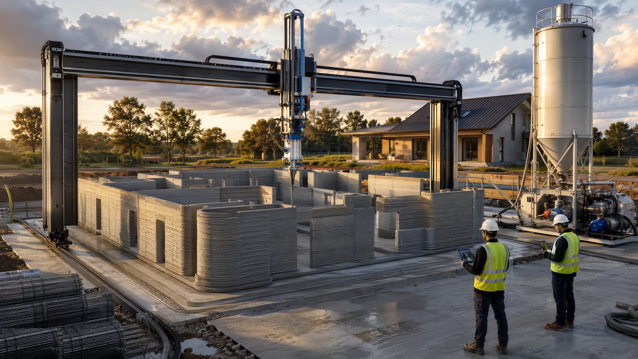
Printed twin-shell construction is how most printed buildings actually achieve their structural capacity. Rather than relying on the printed material to carry load, the printer produces two parallel shells - the inner and outer faces of the wall, often tied together by printed ribs or a serpentine path between them - and those shells act as permanent shuttering. Reinforcement is placed in the cavity between them and concrete is placed and compacted into it. The finished wall is a reinforced concrete element with a printed skin, and the structural design is a reinforced concrete design that the engineer carries out in the ordinary way.
This arrangement resolves the central difficulty of additive construction. A printed cementitious material laid in layers has limited and directional strength, no continuous reinforcement across the layer interfaces, and no long record of how it performs over decades. A reinforced concrete core has none of those problems. The printing then contributes what it is genuinely good at - forming complex geometry without formwork, producing curved and non-repeating walls at little extra cost, and eliminating the strike, cleaning and storage of conventional shutters. It also produces a wall that can be given a designed cavity, insulation and service routes as part of the printed geometry rather than as later additions.
The method is still emerging, and it is treated as such. The engineer designs the reinforced concrete element and specifies the reinforcement and the concrete; the approving authority accepts the proposal case by case; and the printed shells have to be shown to be capable of resisting the pressure of the fresh concrete without deforming or bursting. That last point is the practical crux of the technique. The shells are formwork, and formwork has to be designed for the load it will carry - which means the pour rate, the lift heights and the sequence are all matters for the temporary works designer, established by trial before production. A shell that fails during a pour is an expensive and messy failure, and the discipline that prevents it is exactly the discipline that governs any formed concrete pour: know the pressure, know the capacity, and control the rate.
How does Printed twin-shell with reinforced fill work, step by step?
- 1
Step 1: Design the element as reinforced concrete
The engineer designs the wall as a reinforced concrete element, determining the concrete section, the reinforcement, the connections to the foundations and floors, and what if anything the printed shells are assumed to contribute. On most projects the shells are taken as permanent formwork and a finish, and the structure is entirely in the reinforced core. The approving authority is engaged early and accepts the proposal case by case, since the method is not covered by settled precedent.
- 2
Step 2: Design the shells as formwork
The printed shells have to resist the pressure of fresh concrete, so they are designed for it. The temporary works designer sets the shell thickness and geometry, the tie and rib arrangement between the shells, the permitted pour rate, the lift heights, and any external propping or restraint. These are the parameters that control the pour, and they are established by trial on a representative section before production begins rather than assumed. Cavity width, insulation and service voids are designed into the printed geometry at this stage because they cannot be added later.
- 3
Step 3: Prepare the base with starters in place
Printing starts from an accurately set-out foundation or slab with starter reinforcement already projecting into the cavity position and services already provided for. Getting the starters in the right place matters more here than in almost any other stage, because once the shells are printed the cavity is a fixed and narrow space and there is very little room to correct a misplaced bar.
- 4
Step 4: Print the shells
The printer lays the two shells and their connecting ribs in continuous layers, forming the cavity between them along with the openings, service routes and any features designed into the geometry. Print parameters - speed, extrusion rate, layer height and interval - are those established in trial. Layer bonding matters structurally here too, because the shells must hold together under concrete pressure, and a poorly bonded layer interface is where a shell will split.
- 5
Step 5: Fix reinforcement in the cavity
Reinforcement is fixed in the cavity to the engineer's design, tied to the starters and lapped as specified, with cover maintained to the inner faces of the shells by spacers. Access is restricted and the work is fiddly - which is why the cavity dimensions, the bar arrangement and the fixing sequence are planned with the reinforcement in mind rather than left to be worked out on site. The reinforcement is inspected and signed off before any concrete is placed, because it is completely concealed afterwards.
- 6
Step 6: Place the concrete in controlled lifts
Concrete is placed in lifts at the rate the temporary works design allows, so that the pressure on the shells stays within their proven capacity. The pour is compacted by whatever method the designer has specified for the section - a narrow cavity with congested reinforcement is a place where self-compacting concrete is often preferred to vibration, but that is a decision for the designer and not for the gang. Shells are watched throughout the pour for deflection, bulging or leakage, and the pour is stopped if anything moves.
- 7
Step 7: Complete the structure conventionally
Floors, roof, connections and the remaining structure are built in the usual way, tying into the reinforced core rather than into the printed shells. Construction joints between pours are located and prepared as the engineer requires. From this point the project behaves like an ordinary reinforced concrete building with an unusual finish.
- 8
Step 8: Cure, inspect and finish
The concrete is cured as specified and the element is inspected - shells for cracking, splitting or displacement caused by the pour, and the wall as a whole for verticality and dimensional accuracy against the model. Where there is doubt about the completeness of the fill, the engineer decides what verification is required. The printed outer face is then left exposed, rendered, coated or clad as the design intends.
What are the benefits of Printed twin-shell with reinforced fill?
- Structural capacity comes from designed reinforced concrete, which the engineer can design conventionally
- The printer does what it is best at - complex geometry with no formwork to make, strike, clean or store
- Curved and non-repeating walls cost little more than straight ones
- Cavity, insulation and service routes can be designed into the printed geometry rather than added later
- Permanent shuttering means no strike, no shutter damage and no formwork waste
- Reduces the reliance on the printed material's own long-term structural performance, which is the least proven part of the method
What are the limitations of Printed twin-shell with reinforced fill?
- The shells are formwork and must be designed and proven for concrete pressure, which limits the pour rate
- A shell failure during a pour is a serious, messy and expensive event
- Fixing reinforcement in a narrow printed cavity is awkward and needs planning at design stage
- Once concreted, everything in the cavity is concealed - inspection has to happen before the pour, not after
- Combines two trades and two sets of plant, so both the printing and the concreting have to go right
- Still an emerging method, with the approvals route and durability record developing and case-by-case acceptance
- Complex geometry can make full compaction and complete fill difficult to achieve and to verify
What is Printed twin-shell with reinforced fill best suited for?
What plant does Printed twin-shell with reinforced fill need?
- Gantry or robotic arm printer with print head, control system and delivery line
- Batching or mixing plant for the printable material, with consistent continuous output
- Separate supply of structural concrete, by ready-mixed delivery or site batching
- Concrete placing equipment - pump, skip or tremie - suited to a narrow cavity
- Compaction equipment as specified, or a self-compacting mix where the designer requires it
- Reinforcement fixing equipment, spacers and access suited to working in a confined cavity
- External propping or restraint to the shells where the temporary works design requires it
- Survey equipment and weather shelter over the printing operation
How is Printed twin-shell with reinforced fill quality-checked?
- Reinforced concrete design and approvals route agreed with the engineer and the approving authority
- Shells designed as formwork, with pour rate, lift heights and restraint proven by trial before production
- Starter reinforcement position surveyed and confirmed before the shells are printed
- Print parameters recorded and layer bonding inspected, since the shells must resist concrete pressure
- Reinforcement inspected and signed off in the cavity before any concrete is placed
- Concrete placed in the designed lifts at the designed rate, with the shells monitored throughout the pour
- Concrete testing and curing records kept in the normal way for a structural element
- Post-pour inspection for shell cracking or displacement, and dimensional survey against the model