Precast frame around a slipformed or jump-formed core
A fast in situ core leads the building, with a precast frame erected around it as it rises.
Last updated 2026-09-05
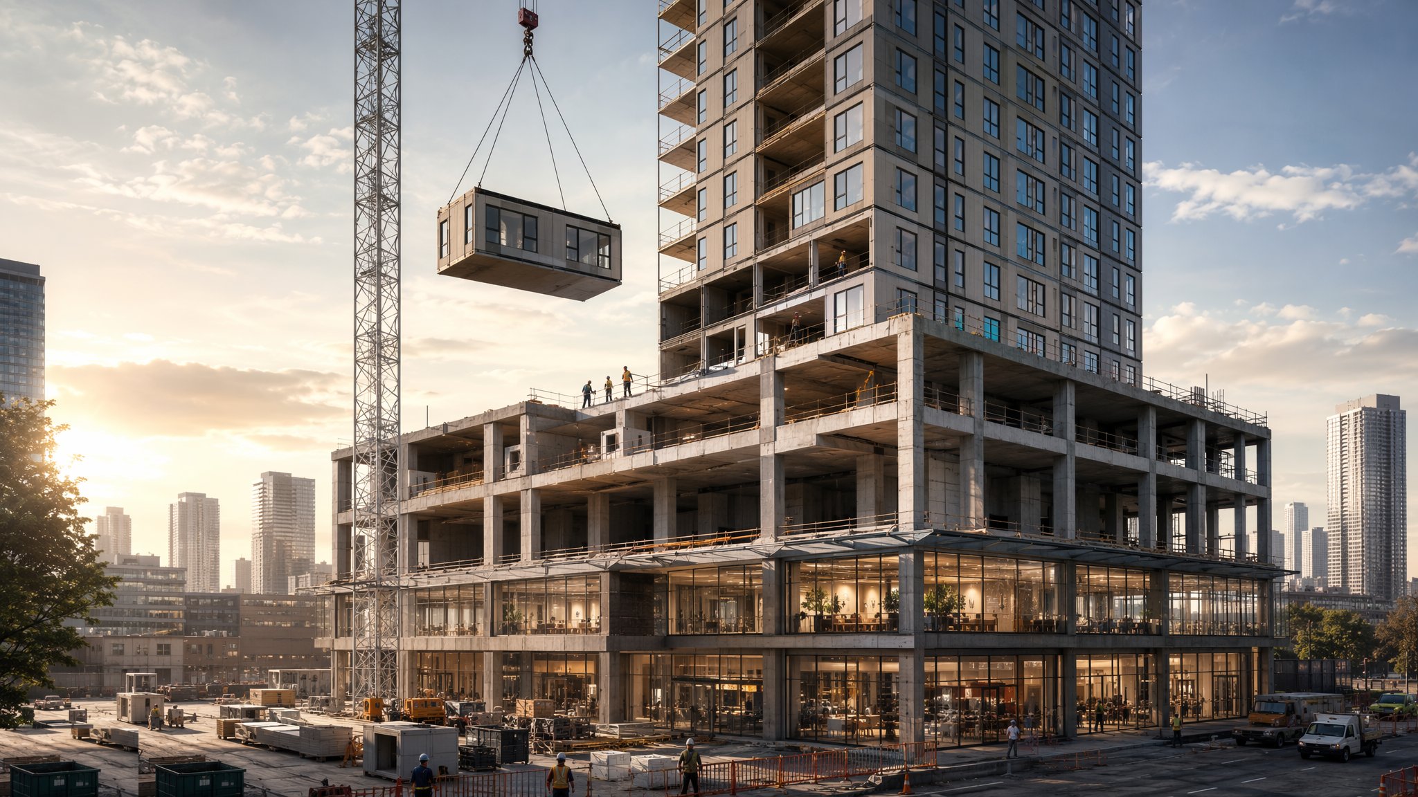
What is Precast frame around a slipformed or jump-formed core?
This is the classic hybrid for a medium or tall building. The core - lift shafts, stairs, risers and the stability walls - is built in situ by slipform or jump form and runs several floors ahead of everything else. Around and behind it, a precast concrete frame of columns, beams, floor units and stair flights is erected floor by floor. The core provides the stability and the vertical circulation. The precast provides the floor plate quickly, cleanly and with a finish that often needs no further treatment.
The logic is that each method leads where it is strongest. In situ concrete is the natural way to build a tall, continuous, heavily reinforced shear element, and a climbing or slipping form is the fastest way to build it. Precast is the natural way to build a repeated floor plate, because the units are made under cover to close tolerances while the core is going up, and erection is an assembly operation rather than a wet trade. Running them in parallel compresses the programme in a way that neither could achieve alone, and it means the crane is serving two quite different operations that have been deliberately arranged not to clash.
The interface is the connection between the precast frame and the core, and it is where the difficulty lives. Precast units are made to factory tolerances. An in situ core, however well built, is made to site tolerances and will have wandered slightly on its way up. Bringing a precast beam to a core wall therefore needs a connection with enough adjustment designed into it to absorb that difference - corbels, embedded plates, pockets, dowels, projecting bars into a stitch pour, or a combination. The positions of those cast-in items have to be set in the core as it climbs, at a moment when nobody is thinking about the precast yet, and getting one of them wrong at floor twelve is discovered months later with a beam on the hook. Tolerance control at this interface is the single recurring failure point of the method, and the designer sets both the tolerances and the adjustment available before either system starts.
How does Precast frame around a slipformed or jump-formed core work, step by step?
- 1
Step 1: Design the two systems and their interface as one
The frame layout, the core geometry and the connection between them are designed together. The designer decides how the floor plate spans, where the precast bears on the core, what carries the horizontal loads back into the core, and how much adjustment each connection needs to absorb the difference between factory and site tolerance. The stability of the frame at every stage of erection - not only when complete - is part of this design, because a precast frame with a core that is ahead of it is a different structure at every floor. Getting this settled before either the core form or the precast moulds are made is what makes the method work.
- 2
Step 2: Fix the cast-in items and mark them on the core drawings
Every plate, pocket, corbel, dowel and projecting bar that the precast will eventually connect to has to be cast into the core at the right level and the right position. Those items are marked on the core reinforcement drawings, checked before each core pour, and recorded once cast. This is the least forgiving part of the process because the core is climbing quickly and the precast is months away. A checking regime that runs level by level as the core rises, against the precast layout rather than only against the core drawing, is what prevents the discovery of a missing plate at erection.
- 3
Step 3: Build the core ahead of the frame
The core is slipformed or jump-formed, working several floors ahead. Its own temporary works, striking or climbing criteria, verticality control and safety arrangements govern that operation. Verticality control matters twice over here: once for the core itself, and once because the precast frame is being made to fit where the core is supposed to be. The as-built position of the core is surveyed as it rises and issued to the precast designer, so that any drift is known and accommodated before units are cast rather than discovered when they arrive.
- 4
Step 4: Manufacture the precast against the surveyed core
Precast units are produced in the factory while the core climbs. Production is scheduled to the erection sequence, because units are erected in a fixed order and storing them is expensive. Unit dimensions, the position of every fixing, lifting anchor and service void are set from the design and, where the core survey shows drift, adjusted before casting. Units are marked, and their handling and lifting points are recorded, because a unit lifted from the wrong points can be damaged before it ever reaches the building.
- 5
Step 5: Erect the frame floor by floor, checking as you go
Columns, beams, floor units and stairs are craned in and set to the survey control, propped and braced as the temporary works design requires. Every floor is checked for level and position before the one above starts, because errors accumulate vertically. Temporary stability is the governing risk during erection: a partly erected precast frame is stable only because the props, braces and connections say it is, and each of those has a design and an inspection behind it. Propping is released only when the designer's criteria are met and the release is recorded.
- 6
Step 6: Make the connections into the core
Where the frame meets the core, the connection is made as the designer detailed - bearing onto a corbel with a restraint fixing, welding or bolting to an embedded plate, dowelling into a pocket, or lapping bars into a stitch pour. The adjustment designed into the connection is used to take up the tolerance difference, and how much adjustment has been used is recorded, because using it all at a low level leaves nothing for the levels above. Any connection that cannot be made as drawn goes back to the designer rather than being modified on the deck.
- 7
Step 7: Complete the structural stitching and topping
The frame becomes a structure when the connections are complete: grouting to bearings, stitch pours between units, in situ topping to the floor where the design calls for it, and the tying reinforcement that makes the floor act as a diaphragm carrying wind loads back into the core. Each of these is a hold point with an inspection before it is covered. Until they are done and accepted, the frame remains dependent on its temporary propping, and the sequence of release has to follow the design rather than the desire to recover props.
- 8
Step 8: Follow on with facade, services and finishes
Behind the erection, the facade is fixed to the frame using the cast-in brackets provided, services are distributed from the core risers into the floors, and fire stopping is completed at every junction between precast units and between the frame and the core. The precast soffits are frequently left exposed, so protection during the following trades is a real requirement rather than a nicety. As-built records of connection positions, stitch pours and prop releases are compiled floor by floor as the building rises.
What are the benefits of Precast frame around a slipformed or jump-formed core?
- Core and frame proceed in parallel, compressing the overall programme substantially
- In situ core gives a continuous, stiff stability element built by the fastest available method
- Precast floor plate erects as a dry assembly, with fewer trades and less material handling on the deck
- Precast units are made under cover to close tolerances while site work continues
- Good, often exposed, soffit finish with little or no follow-on treatment
- Predictable, repeatable floor cycle once the erection sequence settles
What are the limitations of Precast frame around a slipformed or jump-formed core?
- Tolerance between a factory-made frame and a site-built core is the recurring failure point
- Every cast-in item for the frame must be placed in the core months before it is used
- Core drift has to be surveyed and fed back to the precast designer before units are cast
- Erection sequence is fixed, so factory production and delivery must follow it exactly
- Temporary stability during erection is entirely dependent on designed propping and bracing
- Craneage governs the programme, and the core and frame are competing for the same crane
What is Precast frame around a slipformed or jump-formed core best suited for?
What plant does Precast frame around a slipformed or jump-formed core need?
- Slipform or jump form system for the core with its own platforms and jacking or climbing gear
- Tower crane sized for the heaviest precast unit at the working radius, serving both operations
- Precast delivery vehicles, marshalling arrangements and unloading area
- Propping, bracing and temporary restraint designed for the erection stages
- Mobile access platforms for connection work, grouting and fire stopping at the interfaces
- Survey instruments for core verticality and for setting each frame level
How is Precast frame around a slipformed or jump-formed core quality-checked?
- Interface design, tolerances and available adjustment agreed before core form or precast moulds are made
- Cast-in plates, pockets, corbels and dowels checked against the precast layout before every core pour, and recorded once cast
- Core verticality and as-built position surveyed as it rises and issued to the precast designer before units are cast
- Each precast level checked for level and position before the level above is erected
- Propping and bracing installed to the temporary works design and released only against the designer's criteria, with the release recorded
- Grouting, stitch pours, tying reinforcement and topping inspected as hold points before being covered