Slipform
A form that never stops moving, rising continuously through a round-the-clock pour.
Last updated 2026-09-05
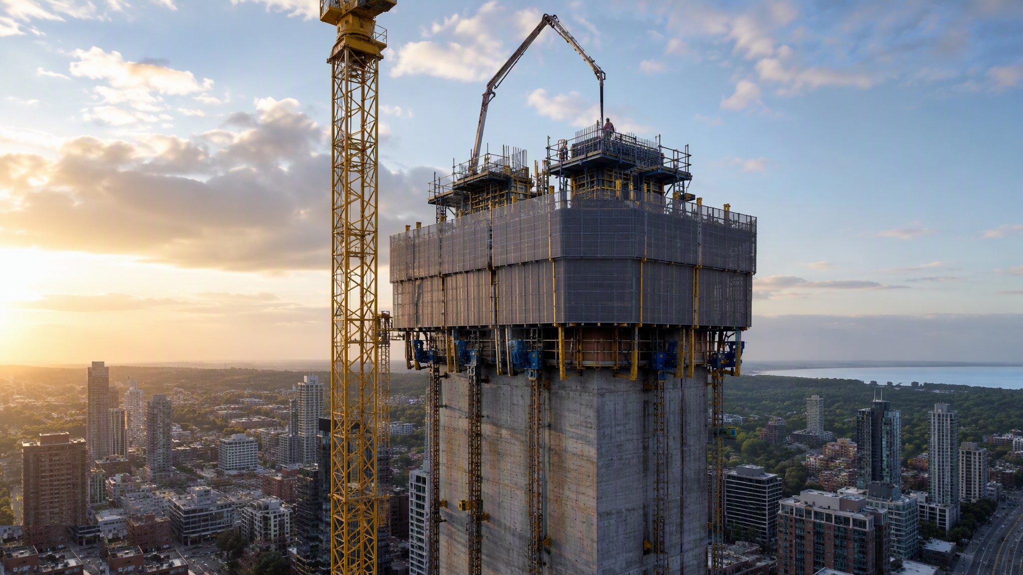
What is Slipform?
Slipform is the only concreting method in common use where the form does not stand still. A relatively shallow form, typically a little over a metre deep, is jacked slowly upwards while concrete is placed continuously into its top. As the form rises, concrete emerges from the bottom having gained just enough strength to stand up on its own. The result is a wall with no lift joints at all, rising continuously for the whole height of the element. The rate of climb is what makes it work: fast enough to keep ahead of the concrete stiffening against the form face, slow enough that the concrete leaving the bottom will not slump. On most projects that rate is measured in a few hundred millimetres an hour, which is why a slipformed core can rise several metres in a day.
Because the form never stops, neither does the project. Slipforming is a round-the-clock operation with shift crews, continuous concrete supply, reinforcement fixed ahead of the form as it climbs, and a full complement of survey, hydraulics and supervision running at three in the morning as at three in the afternoon. Everything the operation needs has to be delivered to a moving deck: concrete, steel, cast-in items, people. The organisation required is closer to a process plant than to ordinary site work, and that is the honest measure of whether a project should be slipformed at all.
The consequence of a stoppage is what everyone in the trade thinks about. If the form stops for long enough, the concrete inside it grips the form face and the operation is in serious trouble - freeing it can require breaking out, and restarting leaves a cold joint that has to be designed, prepared and accepted rather than simply carried on from. So the whole project is built around never stopping: standby concrete plant and a second supply route, standby generation and hydraulic power, spares on the deck, crews rostered with cover, and a written contingency plan for the planned stop as well as the unplanned one. Slipform earns its place on tall, simple, repetitive sections - silos, shafts, chimneys, tall cores, bridge pylons - where its speed is unmatched. It is the wrong choice where the geometry changes often, where openings are numerous, or where the supply chain cannot guarantee continuity. The temporary works designer sets the jacking arrangement, the rate of rise, the yoke and deck design and the conditions for stopping, and those govern the operation.
How does Slipform work, step by step?
- 1
Step 1: Confirm the element suits a continuous rise
Slipform wants height, constant or gently tapering section, and as few interruptions as possible. Openings, embedded plates, beam pockets and changes of wall thickness all have to be formed while the form is moving, and each one is a complication rather than a detail. The designer, the contractor and the slipform specialist review the element together and simplify what they can - aligning openings, standardising thicknesses, moving connections to positions that suit the climb. A project that cannot be simplified enough is usually better jump-formed, and that decision is best made early rather than discovered halfway up.
- 2
Step 2: Design the platform, yokes and jacking system
The temporary works designer designs the whole assembly as one machine: the form panels and their slight taper, the yokes that carry the form, the jacks and their climbing rods, the main working deck with its access and edge protection, and the hanging scaffold below from which the emerging concrete is finished. The design covers the loading of every deck, the arrangement and control of the jacks, the intended rate of rise and how it will be adjusted, the survey and verticality control system, and the procedure for a stop. It also covers the power and hydraulic supply, including redundancy, because a hydraulic failure at height on a moving form is not an inconvenience.
- 3
Step 3: Assemble at the base and prove the system
The form, yokes, decks and jacks are assembled around the base of the element, usually at ground level. Everything is commissioned before the pour starts: jacks stroked and synchronised, hydraulics tested, survey targets and control established, communications proved between the deck, the batching plant and the ground, and the crew briefed on the shift pattern and on who can stop the operation. A trial climb over a short height lets the crew find the rhythm and the supervision confirm the rate before the point of no return. This is the last comfortable moment on the project.
- 4
Step 4: Start the pour and establish the rate of rise
Concrete is placed in the form in shallow layers and compacted, and once enough depth has been built up the jacking starts. The rate of rise is then found and held: fast enough that the concrete is not gripping the form, slow enough that what leaves the bottom stands. The concrete supplied has to be consistent from load to load, because a change in its behaviour changes the rate the form can safely run at. Placing, compaction and jacking settle into a continuous rhythm, and the person supervising the rate is watching the concrete emerging below as much as the gauge on the deck.
- 5
Step 5: Fix reinforcement and form openings on the move
Reinforcement is fixed continuously ahead of the rising form, delivered to the deck and lapped as the wall grows. Openings are formed with boxes fixed in position and left behind as the form passes over them. Embedded plates, couplers, service sleeves and any connection details for the floors are placed to the drawings as the relevant level goes by. There is no going back for anything missed, so a checking regime runs on the deck against a marked-up drawing, level by level, in real time. This is the part of the operation most vulnerable to fatigue on a night shift, and it is checked accordingly.
- 6
Step 6: Control verticality continuously
A slipform will wander if it is allowed to. Verticality and twist are monitored continuously by survey and by the system's own control, and corrections are applied gradually through the jacks. Small, early, gentle corrections work. Large late ones do not, and can distort the form. On tall elements the survey control is run as a discipline in its own right, with results logged every shift and reviewed against the tolerance the designer set, because the position error at the top is the sum of everything that was left uncorrected below.
- 7
Step 7: Finish the emerging concrete from the hanging deck
Below the form face, on the suspended deck, the crew work on the concrete as it appears: rubbing up the surface, making good minor blemishes and curing the fresh face. This has to keep pace with the climb, because the window in which the surface can be worked passes with the form. The hanging deck is part of the temporary works design, is loaded only to what it was designed for, and has its own access and edge protection. Working there means working directly above the previously cast wall with the operation continuing overhead, so the deck arrangement and the exclusion below matter.
- 8
Step 8: Manage stops, then top out and strike down
Every slipform has a written procedure for stopping, planned or unplanned, covering how the form is freed, how the joint is prepared and how the restart is authorised. Standby concrete supply, standby power and hydraulics, spares and cover crews exist so the procedure is rarely used. At the top of the element the form is stopped deliberately at a designed position, the last concrete is finished, and the assembly is dismantled from height and craned down in pieces - a substantial operation planned with the same care as the erection. Records of rate, survey, cast-in items and concrete supply are compiled as the as-built evidence.
What are the benefits of Slipform?
- The fastest way to raise a tall element of constant section - several metres a day is routine
- No lift joints, so the wall is continuous for its full height
- Form, working decks, access and finishing platform all travel as one integrated system
- Crane demand during the climb is low compared with lift-by-lift methods
- Excellent for silos, shafts, chimneys, pylons and tall cores where the geometry repeats
- Concentrates the work into a short, intense period, clearing the element off the critical path early
What are the limitations of Slipform?
- A continuous round-the-clock operation - shift crews, continuous supply and full supervision for the duration
- A stoppage is serious: the concrete can grip the form, and the restart leaves a joint that has to be designed and accepted
- Needs redundancy in concrete supply, power and hydraulics, which is a real cost before anything is poured
- Openings, embedded items and changes of section all have to be handled on a moving form with no second chance
- Verticality drifts unless it is monitored continuously and corrected in small increments
- Not economic for short elements, complicated geometry or projects with an unreliable supply chain
What is Slipform best suited for?
What plant does Slipform need?
- Slipform panels with their yokes, main working deck and suspended finishing deck
- Hydraulic jacks and climbing rods with power packs, plus standby hydraulic capacity
- Continuous concrete supply with a proven second source, and placing equipment on the deck
- Standby generation and lighting for night working
- Survey instruments and continuous verticality monitoring, with logging
- Crane for reinforcement and material delivery to the deck, and for final dismantling
How is Slipform quality-checked?
- Temporary works design covering the assembly, the rate of rise, the deck loadings and the stopping procedure, briefed to every shift
- Concrete consistency checked load by load, because a change in behaviour changes the safe rate of rise
- Rate of rise logged continuously and reviewed against the emerging concrete rather than the programme
- Verticality and twist surveyed every shift, logged, and corrected gradually against the designer's tolerance
- Reinforcement, openings, embedded plates and sleeves checked level by level in real time against a marked-up drawing
- Stoppage procedure, standby supply and cover crews confirmed available before the pour starts, and any stop recorded with the joint treatment agreed