Tunnel form
Walls and slab cast together in one operation, in a room-sized steel form that moves on a daily cycle.
Last updated 2026-09-05
What is Tunnel form?
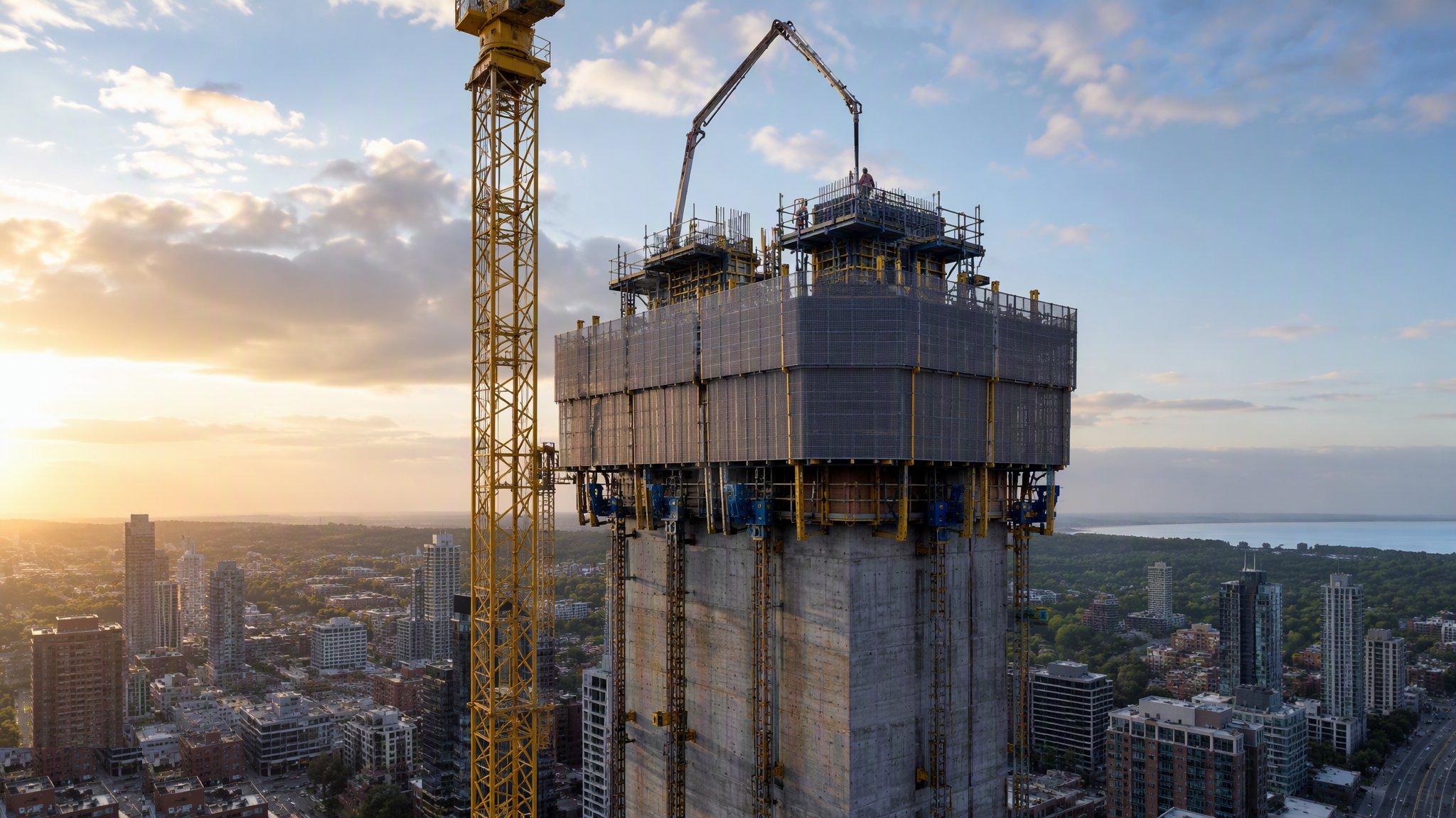
Tunnel form is site-based industrialisation. Instead of building a concrete frame in separate trades - walls first, then a slab, then partitions - a room-sized steel form is set up so that the two walls of a room and the slab over them are cast together in a single continuous pour. The form is made of two half-shells, each an L in section, brought together to enclose the space. Once the concrete has gained the strength the temporary works designer requires, the shells are struck, moved forward or lifted to the next position, and the cycle repeats. The finished structure is a set of concrete cells. There is no separate frame and no separate structural partition, because the walls are the structure.
The method pays where the building repeats. Hotels, student accommodation, apartment blocks, key worker housing and barracks are all made of the same room repeated dozens or hundreds of times, and that repetition is exactly what a tunnel form rewards. A form set of a given room width can be reused floor after floor, and the crew learn the cycle within the first few storeys. A tunnel form commonly turns a floor in a day or two once the crew are running, which is why programmes on repetitive residential towers look so different from the same building in a conventional frame. The counterpart is that the form fixes the geometry. Rooms that vary in width, walls that move between floors and changes late in the design all cut across the economics, because each variation either needs its own form or has to be built conventionally alongside.
The structure that results is exceptionally rigid. Monolithic walls and slabs cast together in the same operation give continuity at every junction, and a cellular arrangement of concrete walls is a very stiff way to resist wind and to spread load. The concrete surfaces come off the steel form flat and dense enough that on most projects they are decorated directly with minimal preparation, which removes plastering from the programme as well. Acoustic and fire performance follow from the mass of the concrete rather than from added layers. The trade-off is that the temporary works are heavy, they work at height, and the cycle only holds if the whole project - concrete supply, craneage, reinforcement, services boxing out, weather protection - is organised around it. The temporary works designer sets the form arrangement, the striking criteria, the props, the ties and the anchorages, and those are checked before every lift.
How does Tunnel form work, step by step?
- 1
Step 1: Test the design for repetition before committing
The first decision is not a construction decision. The designer, the contractor and the form supplier look at the floor plate together and ask how many identical rooms it contains, whether the wall lines stack from bottom to top, and how many different form widths the building really needs. A plan that repeats cleanly makes tunnel form obvious. A plan with a dozen room widths does not. On most projects a short period of design coordination up front - aligning room widths, stacking walls, agreeing where services run - is what turns a marginal case into a good one. This is also where the ground floor and any non-repeating levels are planned, because they are usually built conventionally.
- 2
Step 2: Design the temporary works and the cycle
The temporary works designer takes over the form arrangement. That covers the half-shells and how they are supported, the props and kickers, the ties across the form, the back-propping through the floors below, the working platforms and edge protection, and the criteria the concrete has to satisfy before anything is struck or lifted. It also covers the lifting arrangement, because the shells are craned. None of these figures belong to a rule of thumb. They are calculated for the particular form set, the particular building and the particular crane, issued as a temporary works design, and checked on site before each lift.
- 3
Step 3: Set out and set the first form
Accurate setting out is the whole game, because every subsequent floor inherits the position of the first. Kickers or starter arrangements fix the wall line, reinforcement is fixed to the wall and slab, and the half-shells are craned in, brought together and adjusted to line and level. Ties are fitted, props are set, and the form is checked against the setting-out before any concrete is ordered. On the first few cycles this takes far longer than it will later, and allowing for that learning curve in the programme is the difference between a realistic plan and an optimistic one.
- 4
Step 4: Fix reinforcement, services and the leading edge
Reinforcement for the walls and the slab goes in as one operation, along with anything that has to be cast in: service boxes, conduits, sockets, sleeves, lifting anchors and any connection details for the facade. Because the pour is monolithic there is no second chance to add a penetration cheaply, so the coordination of services with the form has to be settled at design stage and checked on the deck. Edge protection and the leading-edge arrangement are installed as part of the form, not added afterwards, and the crew work from platforms that are part of the system.
- 5
Step 5: Pour walls and slab in one continuous operation
The pour is placed continuously so that the walls and the slab above them become one element with no construction joint between them. That continuity is where the rigidity comes from. The pour rate, the placing sequence and the compaction regime are agreed beforehand, because a form filled faster than the design allowed is a form loaded beyond what it was checked for. Concrete supply has to be reliable enough to keep the pour continuous, and on a daily cycle a delayed delivery does not just cost an hour, it costs the cycle. Weather protection and, in cold conditions, heating and insulation are planned as part of the operation.
- 6
Step 6: Cure, then strike to the designer's criteria
The concrete is cured and protected while it gains strength. Striking - releasing the form and taking the shells away - happens only when the criteria set by the temporary works designer have been met and recorded. Those criteria come from the design of the particular form and structure, and are verified before the form is released. On most projects the cycle is built around accelerating that gain, commonly with heating or insulated blankets, because the striking point is what sets the pace of the whole building. Back-propping to the floors below is installed as the designer specified and stays in place until it is formally released.
- 7
Step 7: Strike, clean, lift and reset
The half-shells are drawn back on wheels or jacks, lifted out through the open face of the building by crane, cleaned, treated with release agent and set in position on the next cell or the next floor. This is the most exposed part of the operation, working at height at an open edge with a large suspended load, and it is planned as a lift with an exclusion zone, a trained slinger and a wind assessment carried out on the day by the person responsible for the lift. The form is inspected each cycle for damage, distortion and worn ties, because a form that has been struck and lifted a hundred times is not the form that arrived.
- 8
Step 8: Follow on and close out the non-repeating work
Behind the moving form come the trades that finish the cells: infill walls to the facade line, stairs and lift shafts where they are not part of the tunnel arrangement, services distribution, and the direct decoration of the concrete surfaces. The stability of the partly built structure at every stage is part of the temporary works design, not an assumption. As-built records of pour dates, strength verification and back-prop release are kept floor by floor, because on a fast cycle the evidence has to be captured as it happens or it is not captured at all.
What are the benefits of Tunnel form?
- Walls and slab cast monolithically, giving a very rigid and continuous structure
- Fast repetitive cycle - a floor commonly turned in a day or two once the crew are running
- Removes separate structural partitions and, on most projects, plastering, because surfaces come off the steel form ready to decorate
- Good acoustic and fire performance from the mass of the concrete rather than from added layers
- Small, stable, highly trained crew rather than many separate trades on the same deck
- Highly predictable programme once the cycle is established, which suits repetitive residential and hotel work
What are the limitations of Tunnel form?
- Only economic where the plan genuinely repeats - varied room widths defeat it
- Wall lines have to stack, which constrains the ground floor and any different uses below
- Heavy temporary works lifted at height at an open edge, needing a designed and checked lifting arrangement every cycle
- High initial cost and a learning curve of several floors before the cycle settles
- Late design changes are expensive because penetrations and boxing out have to be cast in
- The cycle depends on continuous concrete supply, craneage and weather protection - any one of them can stall the whole project
What is Tunnel form best suited for?
What plant does Tunnel form need?
- Tunnel form half-shells sized to the room modules, with their wheels, jacks, ties and props
- Tower crane of sufficient capacity and reach to lift the shells at the building extremity
- Concrete supply, placing booms or skips, and pokers for compaction
- Curing plant - insulated blankets, heaters and enclosures where the cycle depends on early strength gain
- Back-propping and proprietary edge protection integrated with the form
- Reinforcement handling gear, cast-in service boxes and setting-out instruments
How is Tunnel form quality-checked?
- Setting-out of the first form checked and recorded, because every floor above inherits it
- Temporary works design issued, and the form, ties, props and lifting arrangement checked before each pour and each lift
- Reinforcement, cast-in services and penetrations inspected against the drawings before the form is closed
- Pour rate and placing sequence controlled to what the form was designed for, and compaction supervised
- Concrete verified against the striking criteria set by the temporary works designer, with the result recorded before release
- Back-prop installation and formal release recorded floor by floor, and struck surfaces inspected for line, level and finish
More site-based mmc - tunnel form, jump form, slipform, icf methods
Next method
Jump form (climbform)