RTG runways and beamless systems
Rubber-tyred gantries on strengthened pavement strips - cheaper and more flexible, but only as good as the pavement is consistent.
Last updated 2026-09-06
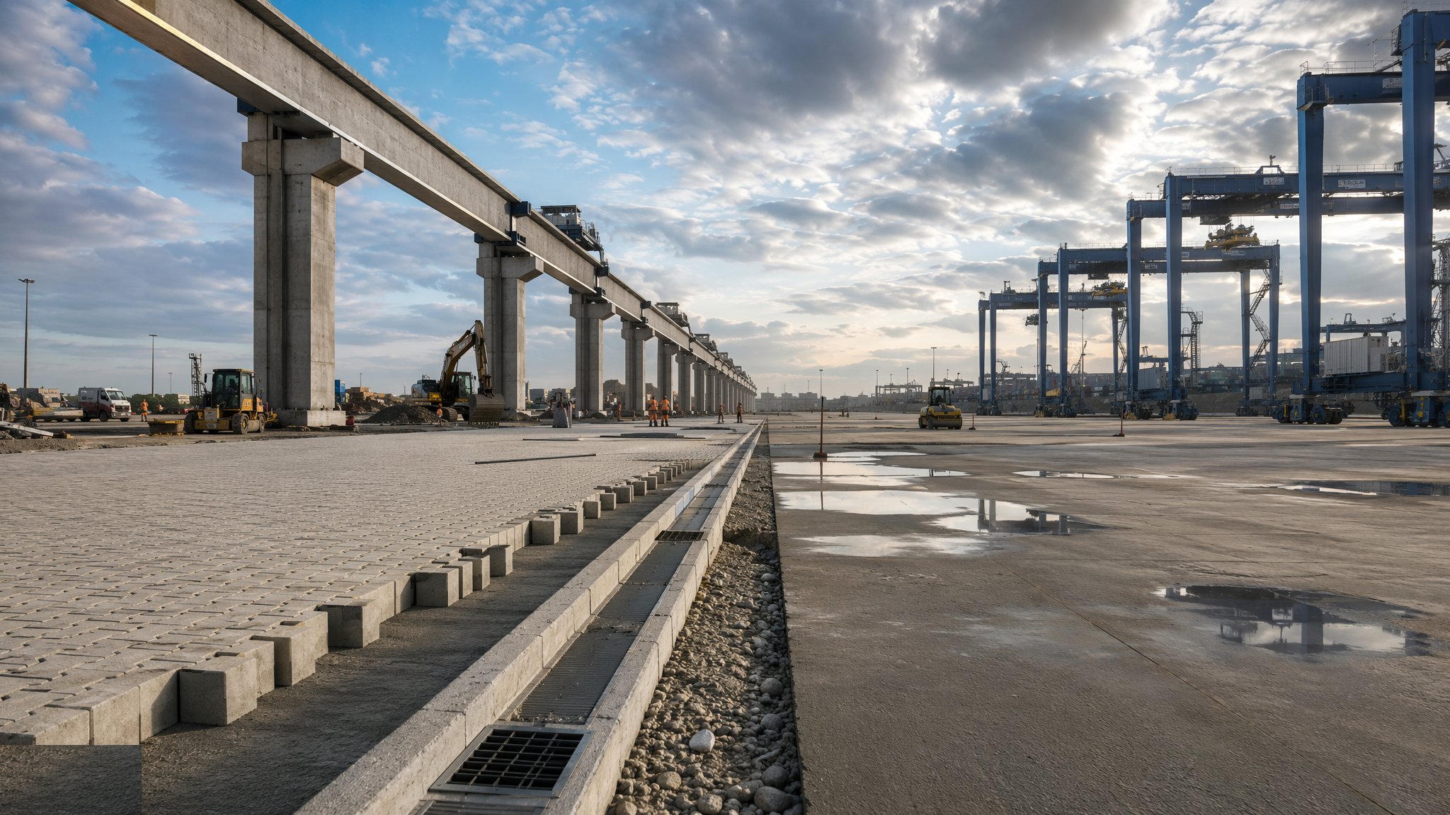
What is RTG runways and beamless systems?
A rubber-tyred gantry does the same stacking job as a rail-mounted machine but runs on tyres instead of rails, steering itself along the yard rather than being guided by a runway. That single difference changes the civil works completely. Instead of a continuous structural beam and rail, the crane runs on the yard pavement itself, usually on strengthened strips built along the wheel paths - the runways. Because there is no rail and no beam, the arrangement is often called beamless, and the whole appeal is flexibility: a stacking block can be reconfigured, extended or relocated with far less civil work than a rail-mounted yard would need.
The engineering problem moves from alignment to consistency. An RTG applies very heavy loads through a small number of wheel groups, repeatedly, in almost exactly the same path. A pavement that is stiff in one place and softer in another will deform differentially, and the crane will start to run out of level, which affects the machine, the stack and the operator. So the runway strips are designed as a stiffer pavement - commonly reinforced concrete strips within a block or asphalt yard - founded and drained so that they behave the same along their whole length, and the transition between the strip and the surrounding surface is detailed rather than left to chance.
Guidance is the other half of the story. Older RTG operations rely on the driver following painted lines, which is workable but produces wander, and wander spreads the wheel loads over a wider strip that then has to be built wider. Automated steering guidance - typically buried or surface-mounted references the machine tracks - narrows the wheel path considerably and lets the runway be narrower and better used, but it puts civil accuracy back into the picture, because the guidance references have to be installed to a tolerance and recorded. On most projects the choice of guidance is made with the crane supplier before the runway is designed, because it changes the width, the reinforcement and the survey requirements of the strip.
How does RTG runways and beamless systems work, step by step?
- 1
Step 1: Agree the machine, the guidance and the block layout
The port operator and the crane supplier settle which machines will work the yard, their wheel arrangement and loads, the stacking block dimensions, the turning and transfer arrangements at the block ends, and whether steering will be manual, line-guided or automated. That decision drives the runway width, because a manually steered machine wanders and an automatically guided one does not. The loads, wheel arrangement and permitted level differences are the crane supplier's data, and the pavement engineer designs the runway to suit them.
- 2
Step 2: Investigate the ground along each runway line
The geotechnical designer looks specifically along the runway lines rather than at the yard as a whole, because uniformity along the wheel path matters more than average quality. Variation in the fill, buried features, old structures and the settlement history of reclaimed ground are all mapped. Where the ground is too variable for a pavement solution the designer may strengthen the formation, treat the ground or, in the worst cases, pile the runway - at which point the cost advantage over a rail-mounted arrangement narrows considerably.
- 3
Step 3: Build the formation and drainage for the whole block
Formation, capping and subbase are built and proven across the block, with the runway lines given particular attention in testing and proof-rolling. Drainage is arranged so that water does not run along or stand in the wheel paths, because saturation of the layers under a heavily loaded strip is the fastest way to lose it. Reefer ducts, lighting and power routes are installed and surveyed, and on most projects they are deliberately routed clear of the runway strips so that later access does not mean breaking into the crane path.
- 4
Step 4: Construct the runway strips
The strips are built as the designer has specified, usually as reinforced concrete cast in continuous lengths within the surrounding pavement, with joints, reinforcement and any load transfer arranged to suit repeated heavy wheel loading in a single path. Levels are surveyed closely along the strip, because it is the change of level along the wheel path rather than the absolute level that troubles the machine. Curing and early trafficking are controlled as for any structural concrete, and the strip is not opened until the specification allows.
- 5
Step 5: Detail the transitions and the block ends
Where the stiff runway strip meets the block paving or asphalt of the surrounding yard, there is a stiffness discontinuity that will attract distress unless it is detailed. The designer specifies the transition, and it is built carefully with proper compaction and edge support. The block ends, where the crane turns or transfers between blocks, take the heaviest and most complex loading of all and are usually built as a full concrete area rather than as strips, sized to the machine's turning arrangement.
- 6
Step 6: Install the guidance references and the power arrangement
Where automated steering is used, the guidance references are installed to the crane supplier's tolerance, surveyed and recorded as-built - they are effectively invisible once the yard is in service, so the record is the only way of finding them again. Where the machines are electrified rather than diesel, the cable reel, busbar or conductor arrangement along the block is installed with its supports, supply points and protection, and coordinated with the lighting and reefer services already in the yard.
- 7
Step 7: Mark out and prove the running with the machine
Lane markings, stacking row numbering and delineation are applied to the completed block. The crane is then run along the full length of each runway, empty and loaded, checking level along the wheel path, tracking behaviour, guidance performance and the transitions at the block ends. Problems found now are cheap; the same problems found after the block is in service mean working around a live stacking operation.
- 8
Step 8: Hand over with a monitoring regime
Because RTG runways depend on continuing pavement consistency, the operator is handed a level survey of each wheel path as a baseline and a regime for re-surveying it periodically, along with the as-built record of services and guidance references. Early deformation along a wheel path is straightforward to correct if it is found; left until the machine complains, it usually means reconstructing a length of strip in a working block.
What are the benefits of RTG runways and beamless systems?
- Far cheaper civil works than a rail-mounted runway, with no beams, rails or fixings
- The stacking block can be reconfigured, extended or relocated with modest civil work
- Machines can be redeployed between blocks, giving the operator real flexibility
- Faster to build, so a block can be brought into service sooner
- No rail trench to drain, maintain and protect from corrosion
- Suits phased terminal growth where the final layout is not yet fixed
What are the limitations of RTG runways and beamless systems?
- Performance depends entirely on pavement consistency along the wheel path
- Repeated heavy loads in a single path make rutting and differential settlement the main risks
- Manual steering causes wander, which forces wider and more expensive strips
- Transitions between the stiff strip and the surrounding pavement are persistent weak points
- Positioning is less precise than a rail-mounted system, which limits automation
- Repairing a runway strip means taking a working stacking block out of service
What is RTG runways and beamless systems best suited for?
What plant does RTG runways and beamless systems need?
- Earthworks and compaction plant with proof-rolling capability along the runway lines
- Concrete paving equipment for the strips and block-end areas, with survey control
- Reinforcement fixing, curing and joint sawing and sealing equipment
- Paving plant for the surrounding block paving or asphalt and the transition details
- Installation and survey equipment for guidance references and electrification supports
- Precision level survey equipment for wheel path baselines
How is RTG runways and beamless systems quality-checked?
- Crane supplier's wheel loads, arrangement and permitted level differences confirmed before design
- Ground investigation and proof-rolling results reviewed specifically along each runway line
- As-built survey of ducts and services confirming they are clear of the runway strips
- Level survey along each wheel path recorded against the specification after construction
- Transition details and block-end areas inspected for compaction, edge support and jointing
- Guidance references surveyed and recorded as-built, with loaded crane trials before handover