Render and EWI systems
A warm overcoat for the building - system-built, bead by bead, or it cracks and lets go.
Last updated 2026-08-25
What is Render and EWI systems?
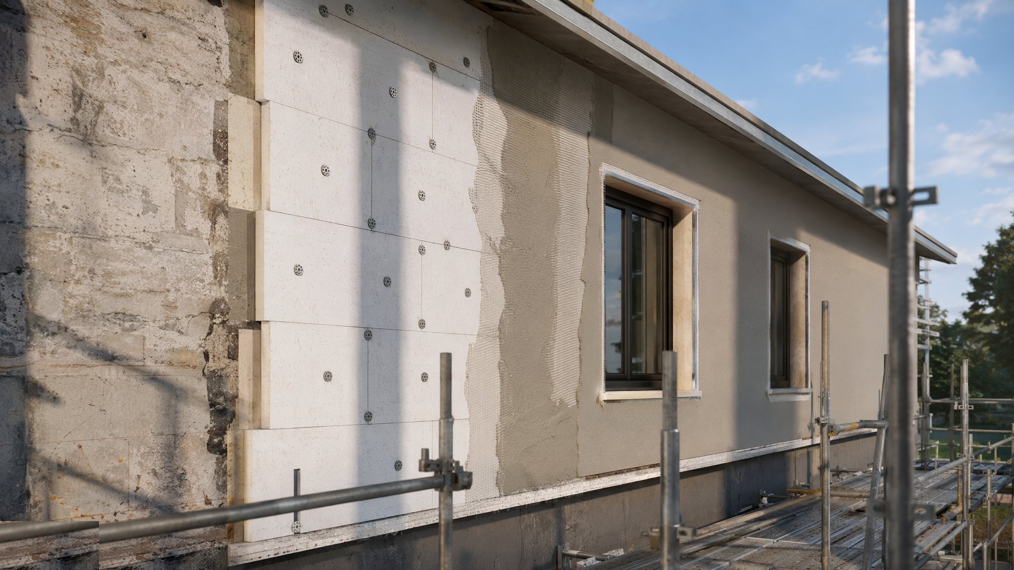
External wall insulation with thin-coat render is the modern answer to two problems at once: how to give a building a clean, contemporary face, and how to wrap it in continuous insulation with no cavity and no cold bridges. The system is fixed as one engineered assembly - rigid insulation boards (EPS, mineral wool or PIR) adhesive-bedded and mechanically fixed to the masonry or sheathed frame, a basecoat with embedded glass-fibre reinforcement mesh, and a thin finish coat of silicone or acrylic render, typically 1.5–3 mm, that gives the colour and the weather face. On new build it wraps the frame; on retrofit it transforms cold, solid-wall housing - EWI is the fabric-first workhorse of the decarbonisation agenda.
Everything about the system is proprietary, and that is the point. These are tested systems - insulation, fixings, basecoat, mesh and finish from one manufacturer with a system certificate - and the certificate lives in the details: base tracks at the damp-proof course line, beads at every opening and movement joint, mesh wrapped around every reveal, minimum render thicknesses over the mesh, and fire-rated fixing patterns with the calculated number and type of anchors per square metre for the building height and wind zone. Site improvisation - a skipped bead, mesh short of a corner, fixings counted by eye - is exactly where EWI fails: cracking at openings, water behind the system, boards letting go.
The discipline is sequencing and environment. Thin-coat renders are fair-weather materials - applied within a temperature window, never on frozen or saturated substrates, protected from sun and rain while curing - and the finish coat is applied elevation by elevation in continuous wet-edge operations to avoid day joints and colour banding. Movement joints in the substrate must carry through the system, never rendered over. The insulation side of the assembly - material choice, U-value build-ups, cold-bridge detailing and the fire-classification rules that decide which insulant is allowed at which height - is covered in full in the Insulation Systems guide; this page keeps to the system build and the render. Here, the fixing records, batch numbers and photographs of the mesh before basecoat are the quality evidence the warranty and the golden thread both demand.
Process storyboard
Step 1 of 6 - slide through the snapshots.
STEP 1
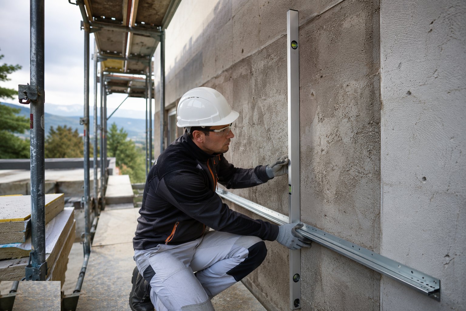
Survey the substrate and set the base track
The substrate is surveyed for line, flatness and soundness - EWI follows the wall it is fixed to, so out-of-true walls are dubbed out or the board thickness…
How does Render and EWI systems work, step by step?
- 1
Step 1: Survey the substrate and set the base track
The substrate is surveyed for line, flatness and soundness - EWI follows the wall it is fixed to, so out-of-true walls are dubbed out or the board thickness varies per the survey. Pull tests prove the fixing capacity into the actual substrate. The base track is fixed level at the DPC line - never below it - and the insulation layout is planned so board joints stagger and no small slivers land at openings.
- 2
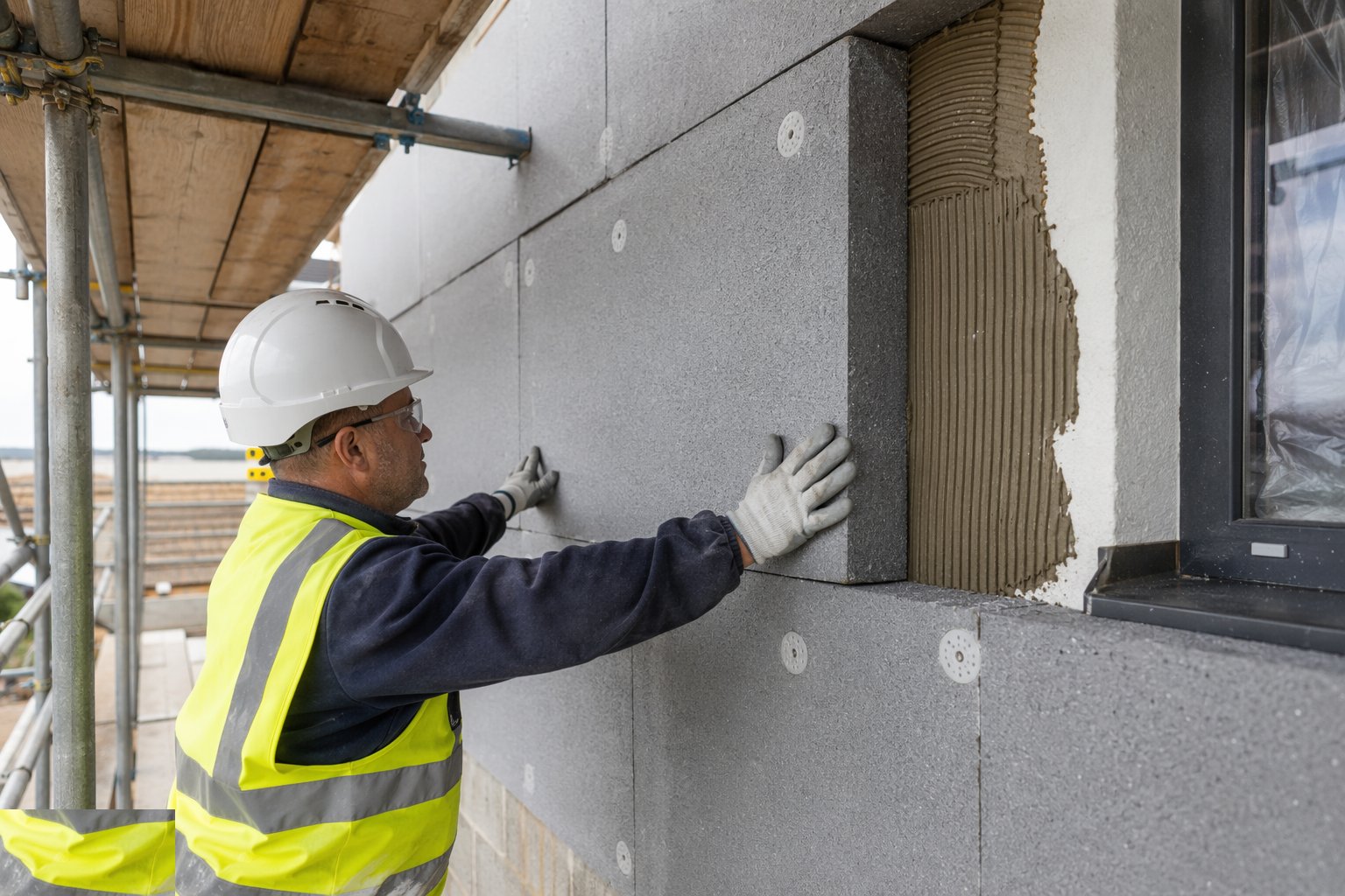
Step 2: Fix the insulation boards
Boards are adhesive-bedded and pressed true, then mechanically fixed with the calculated anchor pattern - typically five or more per board, more in edge zones - with fire-rated fixings where specified. Joints are tight, staggered and gap-filled with the system's foam or slivers, never mortar. Around openings the boards are cut in an L so no joint lands at a corner - the classic crack initiation point.
- 3
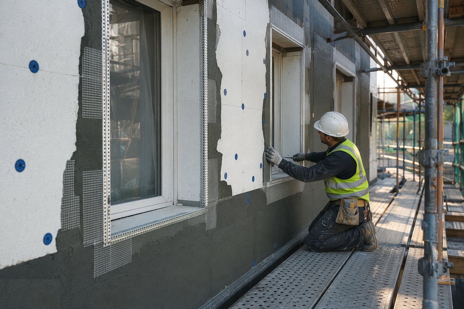
Step 3: Install beads, tracks and reinforcement details
Every opening gets its beads; movement joints get their joint profiles aligned exactly with the substrate joints beneath; bellcast beads form the drip at the base and above every opening head per the design. Additional mesh patches go on at opening corners at 45 degrees - the reinforcement that stops the diagonal cracks everyone has seen and nobody claims. Pipe fixings, brackets and penetrations are fixed through to structure with the system's sealed details.
- 4
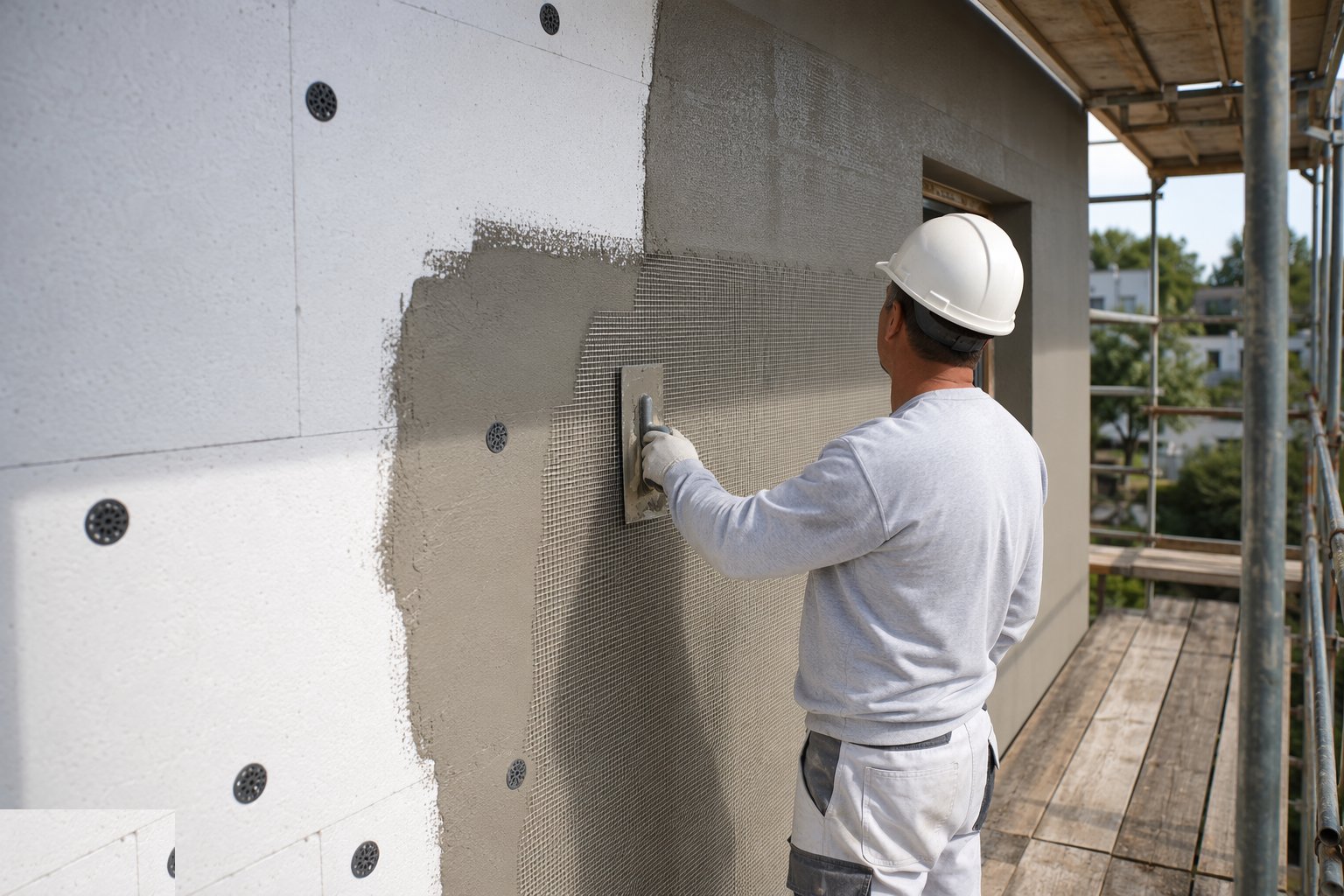
Step 4: Apply the basecoat and embed the mesh
The reinforcement basecoat is applied to the specified thickness and the glass-fibre mesh is embedded top-down into the wet coat, lapped at least 100 mm at joints, wrapped around every reveal, with no dry spots and no mesh showing. Mesh position is in the outer third of the basecoat - buried against the insulation it reinforces nothing. This layer is the system's impact resistance and crack control, and it is photographed before priming.
- 5
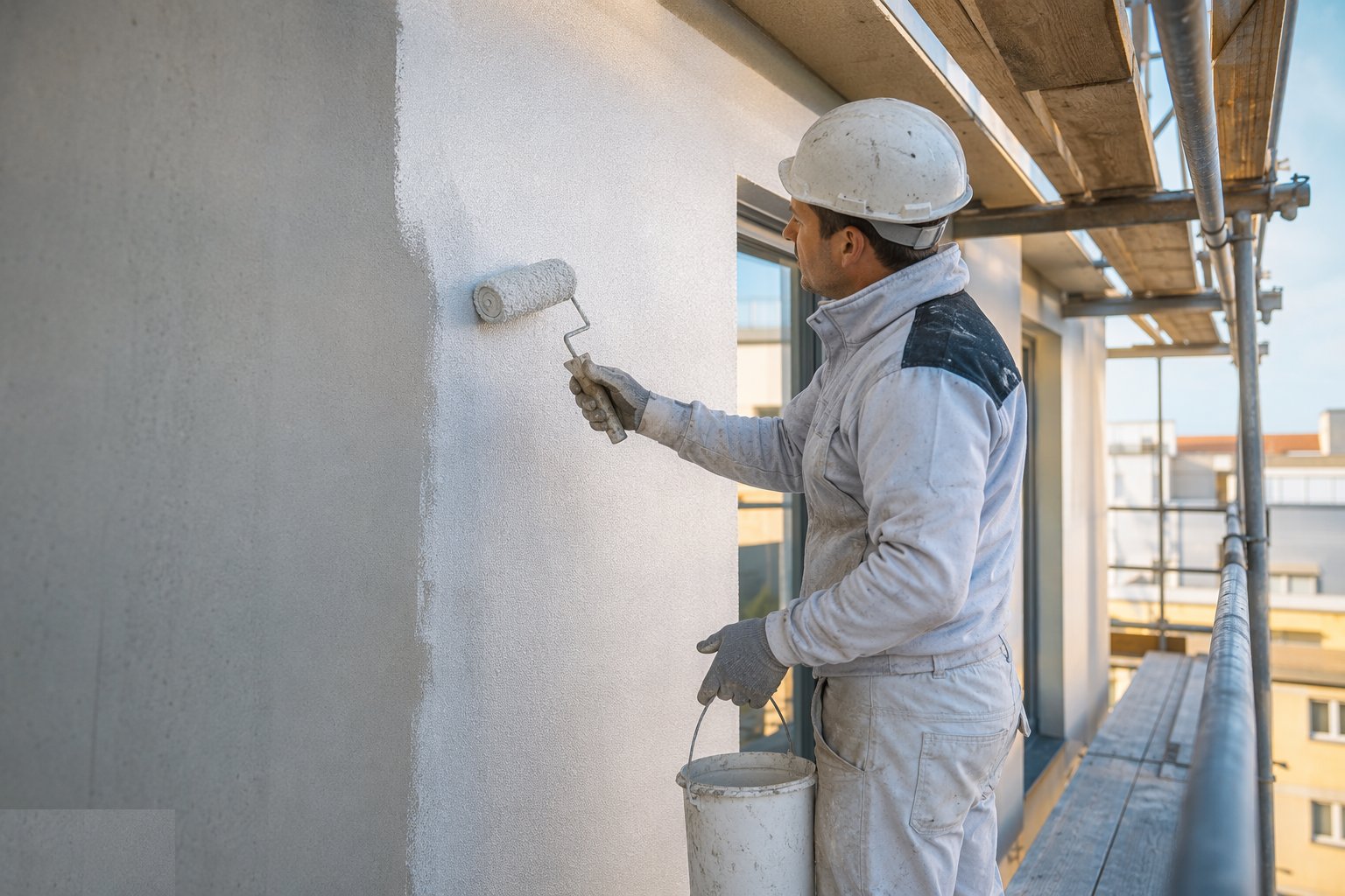
Step 5: Prime and apply the finish coat
After the basecoat cures per the manufacturer, primer goes on and the thin finish coat is applied elevation by elevation in one continuous wet-edge operation per colour batch - same batch numbers per elevation, consistent weather window, no stops mid-wall. Texture is kept consistent across the gang. The finish is protected from rain and frost while it cures, because a washed or frozen finish coat is a rubbed-off and redone finish coat.
- 6
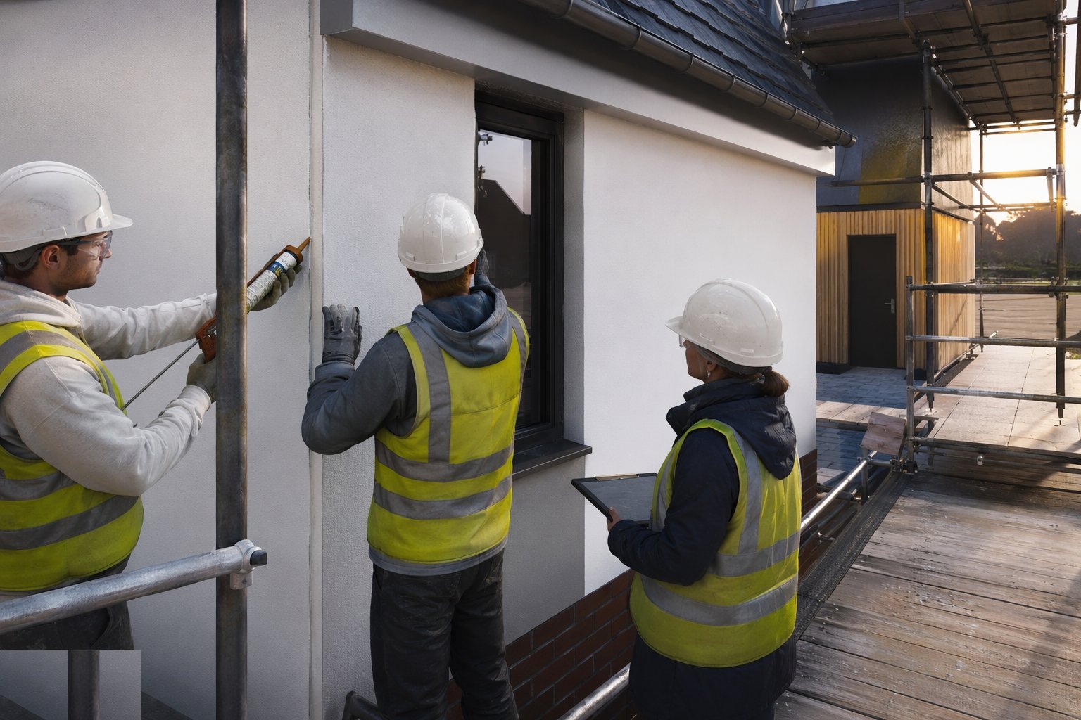
Step 6: Seal interfaces and hand over the system file
Junctions with windows, roofs, paving and dissimilar materials are sealed with the system's specified sealant details, and every penetration is checked for its sealed collar. The QA file is compiled: fixing pull tests and patterns, board and batch records, mesh photographs, weather windows and applicator certification. The manufacturer's warranty issues against the system record - and for taller buildings the fire documentation joins the golden thread.
What are the benefits of Render and EWI systems?
- Continuous external insulation - no cavity cold bridges, dramatic U-value improvement (walls to ~0.18 W/m²K and below)
- Transforms solid-wall and retrofit stock - the fabric-first decarbonisation tool
- Clean modern finish in a wide colour range with low maintenance
- Weather-resistant silicone finishes stay clean and vapour-open
- Keeps the structure warm and dry, protecting it from thermal cycling
- Relatively light - suits existing walls and frames without foundation checks in most cases
What are the limitations of Render and EWI systems?
- Proprietary system discipline is absolute - mixing manufacturers or skipping details voids performance and warranty
- Fair-weather application - temperature windows, rain protection and curing discipline constrain the programme
- Cracking at openings and joints follows any shortcut in mesh and bead work
- Impact damage at ground level needs reinforcement upgrades or protection
- Fire performance depends on the specified build-up - combustible insulation systems carry regulatory limits on height
- Retrofit disrupts rainwater goods, reveals and external details - everything on the wall moves outward
What is Render and EWI systems best suited for?
What plant does Render and EWI systems need?
- Scaffolds or mast climbers with weather protection where required
- Mixing drills and stations for basecoat, adhesive and finish
- Mechanical fixing drivers and the specified anchors, with pull-test kit
- Mesh, beads, tracks and cutting tools
- Render spraying equipment where the system allows
- Weather monitoring - thermometers, and protection sheeting for curing coats
How is Render and EWI systems quality-checked?
- Substrate survey and fixing pull tests recorded before boarding
- Anchor pattern, type and depth verified per elevation against the wind-zone calculation
- Board joints, L-cuts at openings and gap filling inspected before basecoat
- Mesh embedment, laps, corner patches and reveal wraps photographed before priming
- Base track, beads and movement joints checked against the joint layout - nothing rendered over
- Finish batch numbers, weather windows and wet-edge continuity recorded per elevation