3D laser scanning and scan-to-BIM
Stand the instrument up, press go, and the building measures itself - the hard part is what you do with forty million points afterwards.
Last updated 2026-08-25
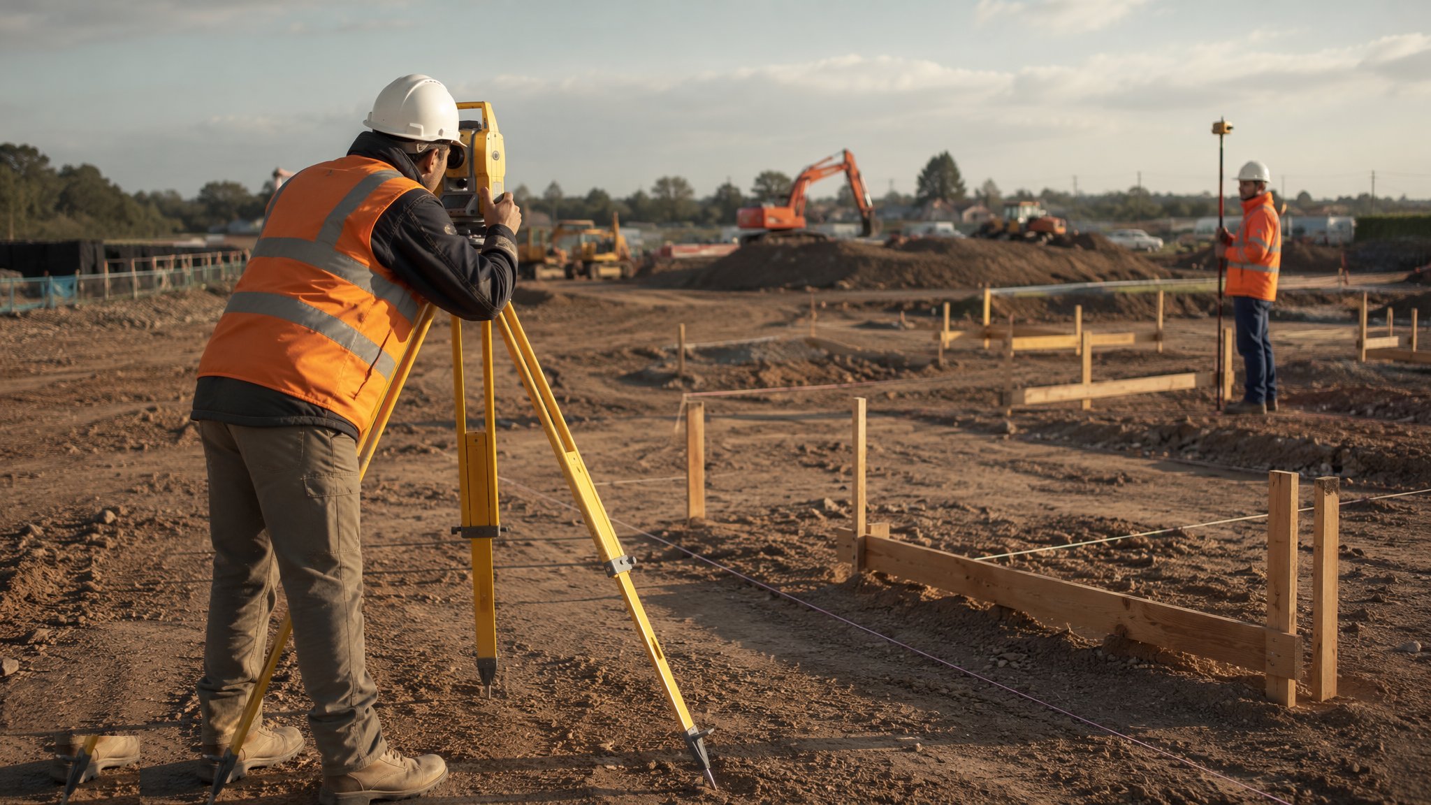
What is 3D laser scanning and scan-to-BIM?
A terrestrial laser scanner sits on a tripod, sweeps a laser through a full dome and records the direction and distance to everything it can see, at rates that commonly run from a few hundred thousand to over a million points a second. One setup takes anything from a couple of minutes at a coarse setting to fifteen or twenty at the finest, and returns a panoramic cloud of tens of millions of points, usually coloured from an on-board camera. Terrestrial instruments commonly work out to 100-350 m, and the resolution is normally set so the surface is sampled every few millimetres at working range - something in the order of 3-10 mm at 10 m for building work. Then you move and do it again. A commercial floor plate might take 20-60 setups; a congested plantroom can take that many on its own, because every pipe hides something behind it.
No single scan is a survey. The scans have to be registered - stitched into one coordinate frame - either from targets that have been placed and surveyed, or by matching the overlapping geometry cloud to cloud, and in practice by both. Registration is where the accuracy is won or lost. Error accumulates as the chain runs down a corridor or up a stair core, so a long thin building will quietly drift unless the registration is tied to independent surveyed control at intervals along it. On a well run job the residuals between scans land in the low single millimetres and stay there across the whole set; on a job registered purely cloud to cloud with no control, they can look excellent locally and be tens of millimetres out end to end. The survey specification sets the accuracy the registration has to achieve, and the registration report is what proves it did.
Scan-to-BIM is the second half of the job, and normally the bigger half of the fee. The cloud is data, not a model: it has no idea which surface is a wall and which is a duct. Someone models the elements the brief calls for, to a level of detail and a level of accuracy agreed before anyone mobilises, and everything not modelled stays as cloud for reference. Get that brief wrong and you have either paid to model plasterwork nobody needed, or received a model that stops exactly where the coordination problem starts. Used properly the pair is powerful - the model to design against, the cloud to check against, and a deviation heat map showing in one picture where the frame that was built differs from the frame that was drawn.
How does 3D laser scanning and scan-to-BIM work, step by step?
- 1
Step 1: Write the brief before anyone mobilises
Agree what the survey is actually for, because that decides everything else. State the coordinate system and datum, the accuracy required, which elements get modelled and which stay as cloud, the level of detail for each, and the deliverables - registered cloud, panoramic viewer, model, plans and sections, or all of them. Agree access too: ceilings lifted, risers opened, plantrooms unlocked. A scan of a closed ceiling is a scan of a ceiling. This half hour is the difference between a survey that answers questions for two years and an expensive folder nobody opens.
- 2
Step 2: Put in survey control first
Establish or pick up the project control and survey the scan targets from it, so the cloud lands in the same coordinate system and on the same datum as the design model. Without that step the cloud sits in its own arbitrary frame and every later comparison is an argument. Spheres and checkerboard targets go where adjacent scans overlap, at varied heights and never all in one plane, and stay put until registration is finished. On a multi-storey job, level is carried up by the same means the setting-out uses, not inferred from the scans.
- 3
Step 3: Plan and shoot the scan positions
Set the positions on a marked-up plan so adjacent scans share a healthy overlap - roughly a third of the view is a working rule - and so every face that matters is seen from at least two directions. Occlusion is the enemy: behind a riser, above a bulkhead, under a stair. Shoot low under soffits and high off a raised tripod where headroom allows. Doors get propped open, ceiling tiles lifted where the brief says so, and people asked to stand still or step out, because anything moving ghosts across the data. Record which scan is which as you go, not from memory that evening.
- 4
Step 4: Register the cloud and report the residuals
Targets give the coarse registration, cloud-to-cloud matching refines it, and the whole set is adjusted together rather than chained one scan onto the last. The output that matters is the residual table - scan by scan, plus the fit to the surveyed control points. Read it properly: a set that fits itself beautifully but sits 30 mm off the control has drifted, and the fix is more control, not more cloud matching. Anything outside the tolerance the specification sets gets re-observed or re-scanned before the data goes anywhere near a modeller.
- 5
Step 5: Clean, classify and publish
Strip out the ghosting - people, forklifts, hanging cables that moved between scans - and the stray returns off glass and wet floors. Unify and decimate to a working density, keeping the full-density data archived, because a 300 GB cloud that crashes every laptop on the project gets ignored. Publish in a form the team can actually use: a panoramic web viewer beats a point-cloud file for nine out of ten questions, because a site manager can stand virtually in the plantroom and measure between two flanges without any software at all.
- 6
Step 6: Model to the brief and run deviation analysis
Model only what the brief calls for, and record the assumptions where the cloud was blind - a bar over an occluded zone is a guess, and it needs flagging as one. Then compare: overlay the design model on the cloud and produce a deviation heat map. That is where the value lands, because it shows the slab that sags 20 mm at mid-span, the column out of plumb, or the façade zone that has closed up, before anything is fabricated to fit it. Out-of-tolerance elements go back to the designer against the criteria the engineer has set, not resolved on site by eye.
What are the benefits of 3D laser scanning and scan-to-BIM?
- Captures everything in view in one visit, so the question nobody thought to ask can still be answered a year later
- Millions of measured points where a tape survey gives dozens - it finds the sag, the twist and the out-of-plumb instead of assuming right angles
- Non-contact and quick on site, so occupied, live or hazardous areas are recorded with minimal exposure and disruption
- Gives offsite fabrication real dimensions to build to, which is where it pays for itself - a riser module that fits first time
- The panoramic imagery is a defensible record of condition on a known date, useful long after the survey is over
- Deviation heat maps show built against designed in a single picture, which no dimensional schedule ever does
What are the limitations of 3D laser scanning and scan-to-BIM?
- It records only what the beam can see - behind pipes, above ceilings and inside voids stay blank unless somebody opens them up
- Registration error accumulates along corridors and up stair cores, so long thin buildings drift without independent control
- Glass, polished metal, standing water and very dark or wet surfaces return poor, missing or false data
- Moving people, traffic and plant leave ghosting that has to be found and cleaned out
- The cloud is a snapshot of one day, and it starts going out of date the moment demolition or construction restarts
- Modelling is the expensive half - a cloud delivered with no modelling brief is an unopened box of data
What is 3D laser scanning and scan-to-BIM best suited for?
What plant does 3D laser scanning and scan-to-BIM need?
- Terrestrial laser scanner on a survey tripod, with on-board camera for colourised data
- Spheres, checkerboard targets and target stands for registration
- Total station or GNSS to survey the targets onto project control
- Controller or tablet for on-site coverage checks before demobilising
- Registration and point-cloud processing software, with a workstation able to run it
- Handheld or trolley-mounted scanning kit for confined spaces and low-value fill-in areas
How is 3D laser scanning and scan-to-BIM quality-checked?
- Survey brief fixes coordinate system, datum, accuracy, level of detail and deliverables before mobilisation
- Targets or control points surveyed from project control - never left in a scanner-local frame
- Registration report issued with per-scan residuals and the fit to control, against the tolerance the specification sets
- Coverage checked against the marked-up plan so occlusions are known and listed, not discovered later
- Independent tape or handheld distance checks on a sample of measurable dimensions
- Any model issued with a deviation analysis against the cloud it was built from