GNSS (RTK) control
Centimetre positions anywhere under open sky - the earthworks surveyor's instrument.
Last updated 2026-08-25
What is GNSS (RTK) control?
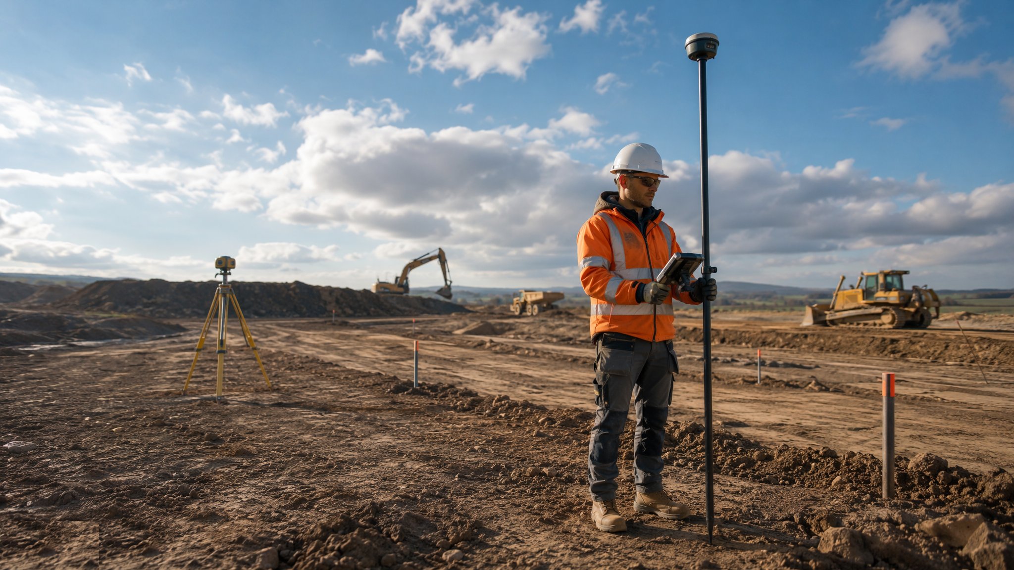
Real-time kinematic GNSS gives centimetre-level positions in seconds, anywhere the receiver can see enough sky. A rover on a pole receives satellite signals plus corrections - from a site base station or a network subscription service - and resolves its position against a fixed coordinate reference in real time. For large open sites, earthworks, drainage and roadworks, it has replaced most traditional setting-out: one person walks the ground, the controller displays cut and fill against the design model, and a day's topo that once took a week takes an afternoon.
The strengths are real and so are the failure modes. GNSS needs satellites: between tall buildings, under tree canopy, in deep cuttings or near big metal structures, the solution degrades or drops to "float" - and the controller will still show a position, just a wrong one. Multipath - signals bouncing off structures - can sit a rover 50 mm off while reporting a fix. The discipline is to work only on a verified fixed solution, to check in on known control at the start of every session, and to treat the instrument's confidence display as gospel.
The coordinate chain is the other place GNSS bites. The instrument works in a global reference frame; the drawings are in a site grid. The transformation - localisation or calibration onto site control - must be computed from surveyed points and verified on independent ones. A wrong transformation parameter moves everything uniformly and invisibly, which is why the daily check-in on a known station is not optional and why the transformation is computed once, checked, and locked.
Process storyboard
Step 1 of 6 - slide through the snapshots.

STEP 1
Establish corrections: base or network
Choose the correction source.
How does GNSS (RTK) control work, step by step?
- 1
Step 1: Establish corrections: base or network
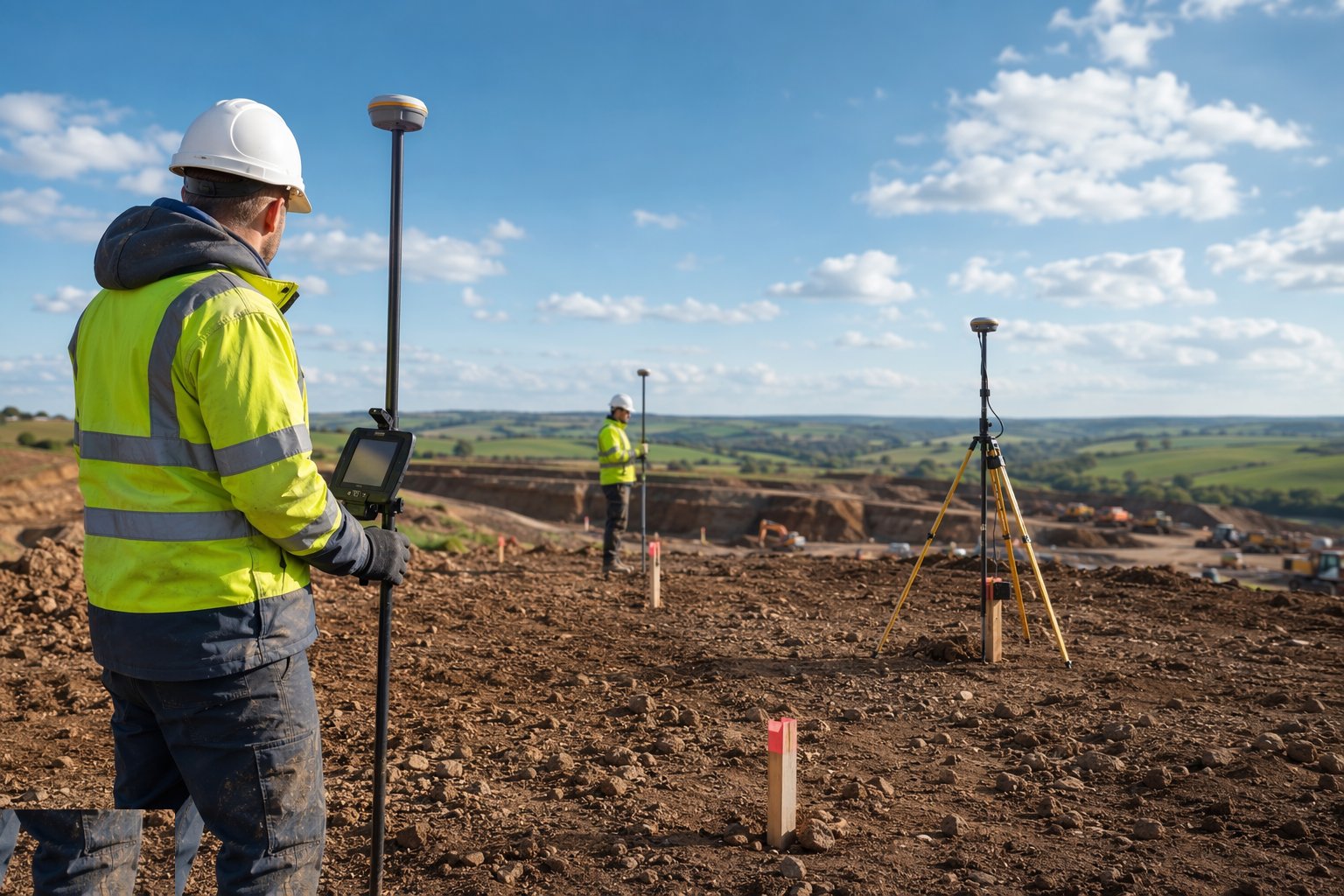
Choose the correction source. A site base station set over a known point gives full independence and works without mobile coverage - but must itself be coordinated and protected. A network RTK subscription needs no base but depends entirely on the phone signal; dead zones are dead surveys. Whichever is used, the correction link is verified before work and monitored during it.
- 2
Step 2: Localise onto the site grid
The transformation from the GNSS reference frame to the site grid and datum is computed from observed control points - at least three, well spread around the site - and the residuals are inspected: any point that does not fit is investigated, not averaged away. The transformation is then verified on independent stations not used in its computation, locked in the controller, and never casually recomputed mid-project.
- 3
Step 3: Check in on known control, every session
Before any setting out or pickup, the rover occupies a known station: the observed coordinates must reproduce the control within tolerance - centimetres, not the instrument's best-case brochure figure. A failed check-in means a lost fix, a disturbed station or a transformation problem, and work stops until it is resolved. This two-minute ritual is the entire quality system in miniature.

- 4
Step 4: Set out and survey on fixed solutions only
Work proceeds only while the controller shows a fixed solution with acceptable precision indicators; on float or standalone, the pole goes down and the operator waits or moves. For earthworks, the controller or machine-control display shows cut/fill live against the design surface. Critical points - foundation corners, drainage inverts - set out by GNSS are checked by an independent method before construction commits.

- 5
Step 5: Feed the machines
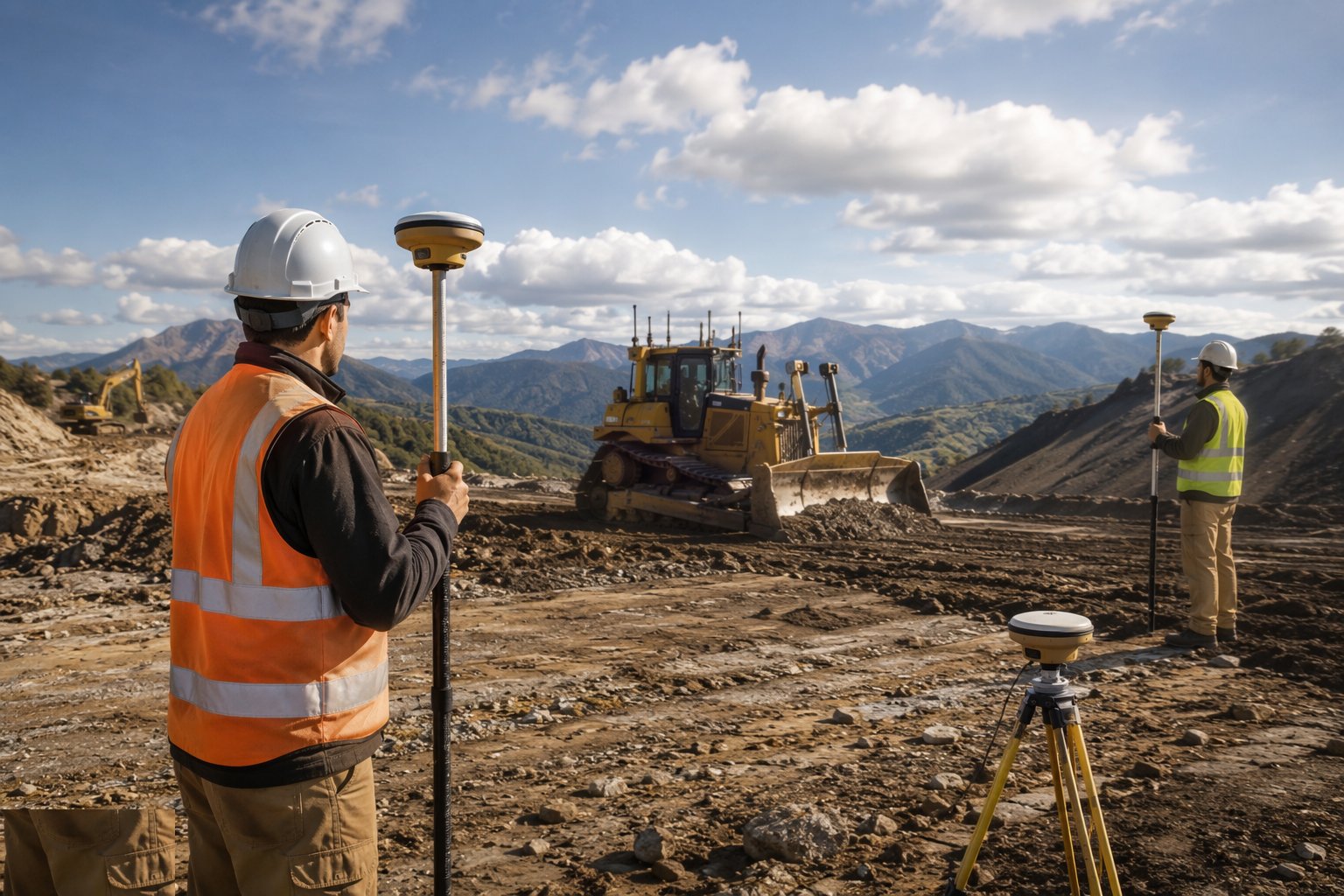
The same localised model drives the machine-control systems on dozers and excavators: the blade follows the design surface automatically, and the surveyor's role shifts from staking to verification - checking formation on a grid with the rover as the dig proceeds. The model on the machine and the model in the controller must be the same issued revision; a version mismatch grades the site beautifully to the wrong design.
- 6
Step 6: Record, verify and archive
Observations, check-ins and set-out records are exported daily and filed - the audit trail for the as-builts and for any later dispute about what was set out when. As-built surfaces are picked up with the same rigour as setting out, on a verified fix, with redundant shots on critical features. At project end the archived raw data and the locked transformation are part of the handover survey file.

What are the benefits of GNSS (RTK) control?
- Centimetre positions in seconds - the fastest method for open-site work
- One operator, no line-of-sight between instrument and target
- Live cut/fill display transforms earthworks setting-out and verification
- Direct feed to machine control - the model drives the blade
- Huge daily pickup capacity for topo and as-built surveys
- No accumulated traverse error across large sites
What are the limitations of GNSS (RTK) control?
- Needs sky view - degrades or fails between tall structures, under canopy, in cuttings
- Multipath near structures can give confidently wrong positions
- Network RTK depends on mobile coverage; a base station depends on power and security
- The localisation transformation is a single point of failure - verify it or lose everything
- Vertical accuracy is inherently weaker than horizontal - drainage inverts deserve a level check
- Float solutions look like positions and must be refused, every time
What is GNSS (RTK) control best suited for?
What plant does GNSS (RTK) control need?
- GNSS RTK rover with controller and pole
- Base station and radio link, or a network RTK subscription
- Survey-grade antenna with known antenna-height conventions
- Machine-control systems on dozers and excavators
- Known, protected check-in stations around the site
- A precise level for independent verification of critical levels
How is GNSS (RTK) control quality-checked?
- Localisation computed from three-plus control points with residuals inspected and filed
- Transformation verified on independent stations before first use
- Check-in on known control at the start of every session, recorded
- Fixed-solution-only rule enforced - precision indicators logged on critical points
- Critical levels and positions checked by independent method (level or total station)
- Daily export and archive of observations, check-ins and issued model revisions