Total station (traverse) control
Angles and distances between known stations - millimetre truth, no satellites required.
Last updated 2026-08-25
What is Total station (traverse) control?
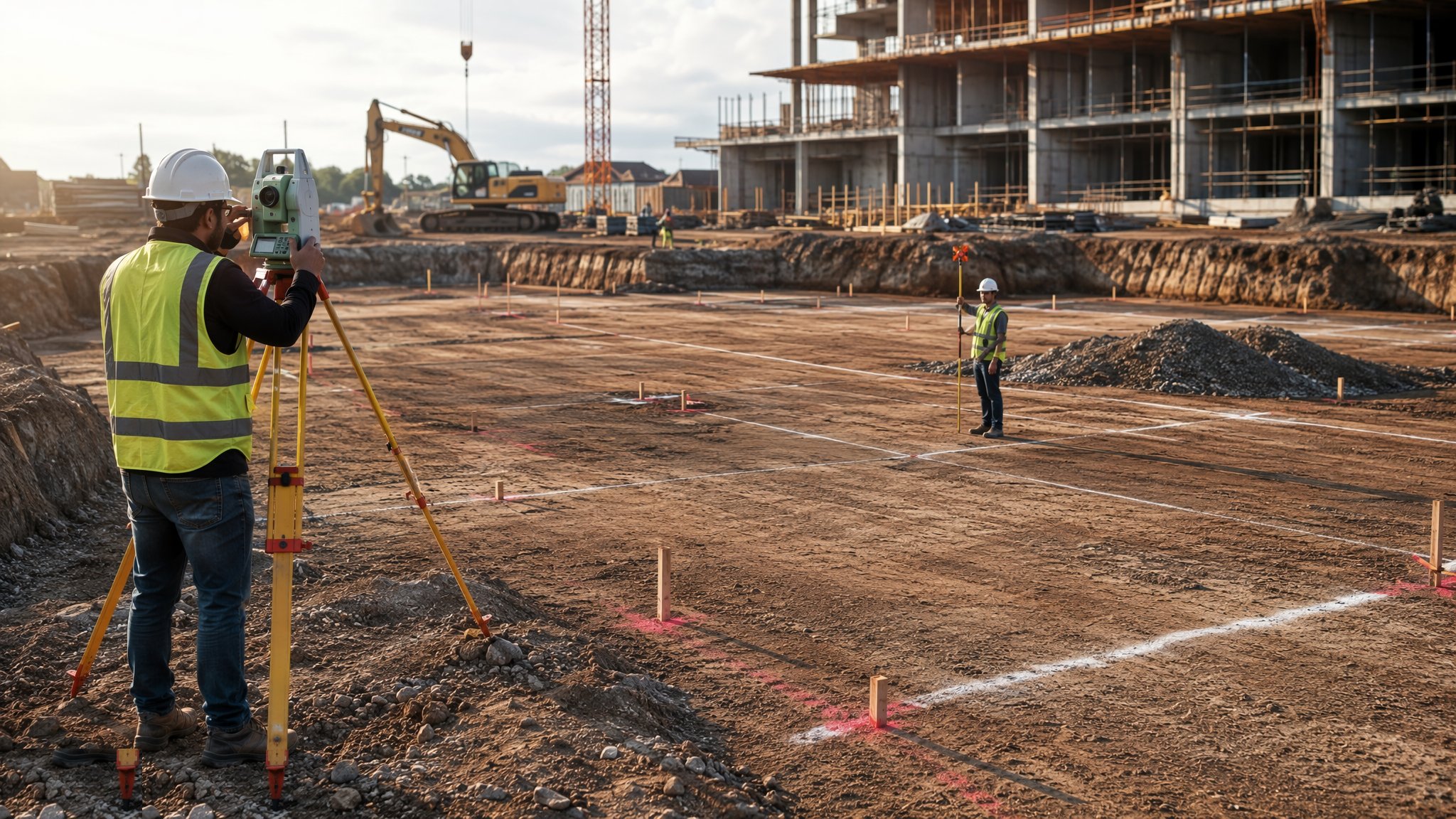
The total station is the building site's primary instrument: an electronic theodolite with a distance meter that measures angles and distances to a prism, computes coordinates, and sets out or checks any point to a few millimetres. Traverse control means establishing a network of fixed stations around the site - observed in a closed loop, adjusted by least squares - so that every set-out point and every check survey traces back to intervisible, verified control. It works between buildings, under canopy, indoors and at night, which is precisely why it remains the workhorse when GNSS cannot see the sky.
The discipline is redundancy. A traverse that does not close is telling you something - a disturbed station, a wrong target height, a misidentified point - and the misclosure tolerance exists so you find out on the instrument, not at the pile-cap inspection. Every set-out point is observed from control, then checked from different control. The peg driven from a single setup, unchecked, is the peg that puts the building 300 mm wrong and the reason check surveys exist.
Modern total stations will track a prism robotically and drive setting-out from a uploaded coordinate file - one person with a pole doing what used to take two. That speed cuts both ways: the instrument will faithfully set out a transposed coordinate from a hand-edited spreadsheet. So the data chain is controlled as tightly as the observations: coordinates extracted from the model, checked by a second person against the drawings, uploaded to the instrument, and never hand-keyed at the peg.
Process storyboard
Step 1 of 7 - slide through the snapshots.
STEP 1
Fix and protect the primary stations
Three or more primary stations go into stable ground outside every working area - steel pins in mass concrete, or survey nails in existing hardstanding -…
How does Total station (traverse) control work, step by step?
- 1
Step 1: Fix and protect the primary stations
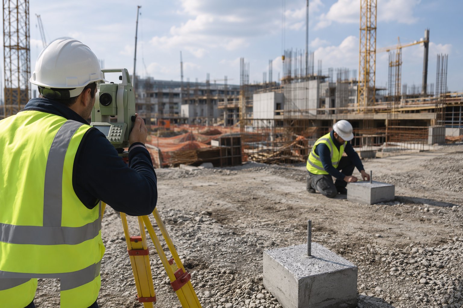
Three or more primary stations go into stable ground outside every working area - steel pins in mass concrete, or survey nails in existing hardstanding - positioned for intervisibility across the whole job and clear of future dig lines, haul routes and crane loads. They are fenced, painted and recorded on the control drawing with coordinates, descriptions and photographs. These stations outlive the project; treat them accordingly.
- 2
Step 2: Observe and adjust the traverse
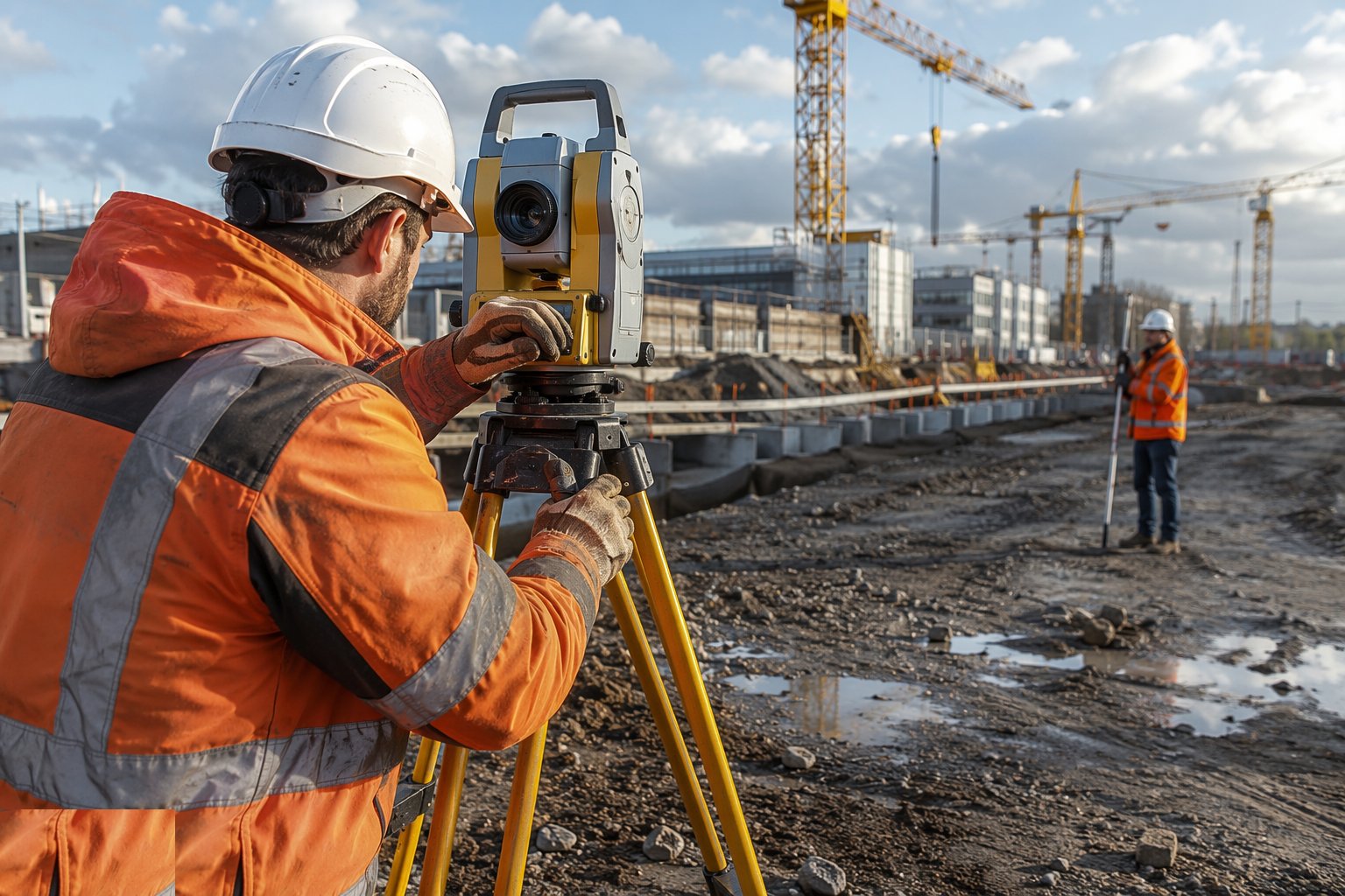
The traverse is observed as a closed loop: multiple rounds of angles and distances at each station, target and instrument heights recorded, atmospheric corrections applied. The loop misclosure is computed against tolerance - a first-order site traverse expects closure in millimetres, not centimetres - and the network is adjusted by least squares. Any station that will not close is re-observed until the network is sound.
- 3
Step 3: Establish the vertical datum
Levels are tied to the project datum by precise levelling from a known benchmark, closing on at least two independent site benchmarks. The level loop misclosure is checked against tolerance - typically a few millimetres times the square root of the distance. Horizontal control without verified vertical control sets out a perfectly positioned building at the wrong height, which is worse, because it is discovered at the drainage connection.

- 4
Step 4: Compute, check and upload setting-out data
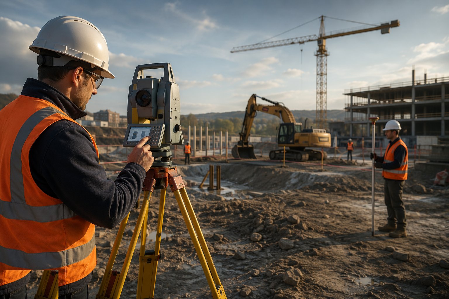
Coordinates for grid intersections, corners and centre lines are extracted from the design model and independently checked against the drawings by a second person - digit by digit on the critical points. The checked file uploads to the instrument. The first point of every setting-out session is a check on a known station: if the instrument does not reproduce the control, nothing gets set out that day.
- 5
Step 5: Set out and mark on profiles
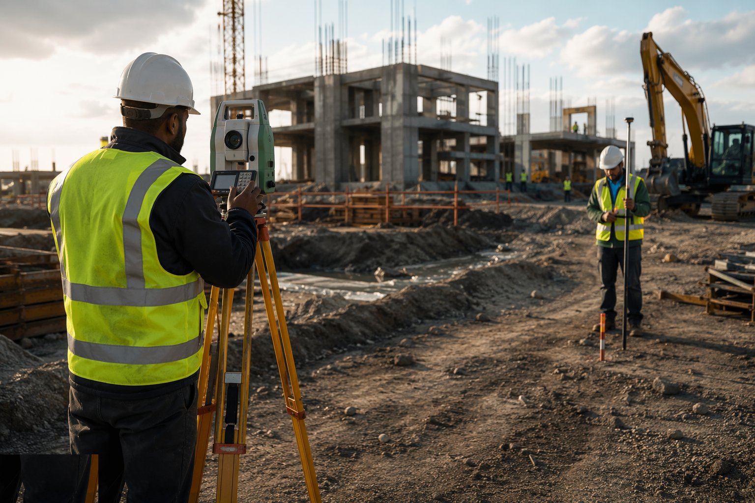
Primary points are set out and marked on profile boards or sight rails set clear of the excavation, with strings giving the trades their working lines. For steel and precast, the tighter tolerance applies - ±5 mm is common where foundations get ±10 mm. Every point set is recorded: what, from which control, to what residual.
- 6
Step 6: Check from independent control
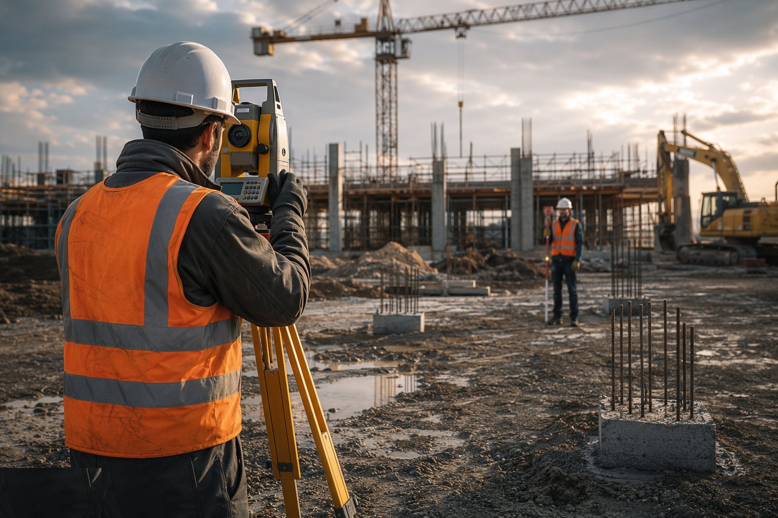
The check survey re-observes the critical points from a different station - or by a second engineer - and compares against design within tolerance. Discrepancies are resolved before handover to the trade, not negotiated afterward. The signed check survey is the document that releases the dig, the blinding or the steel.
- 7
Step 7: Maintain the network for the duration
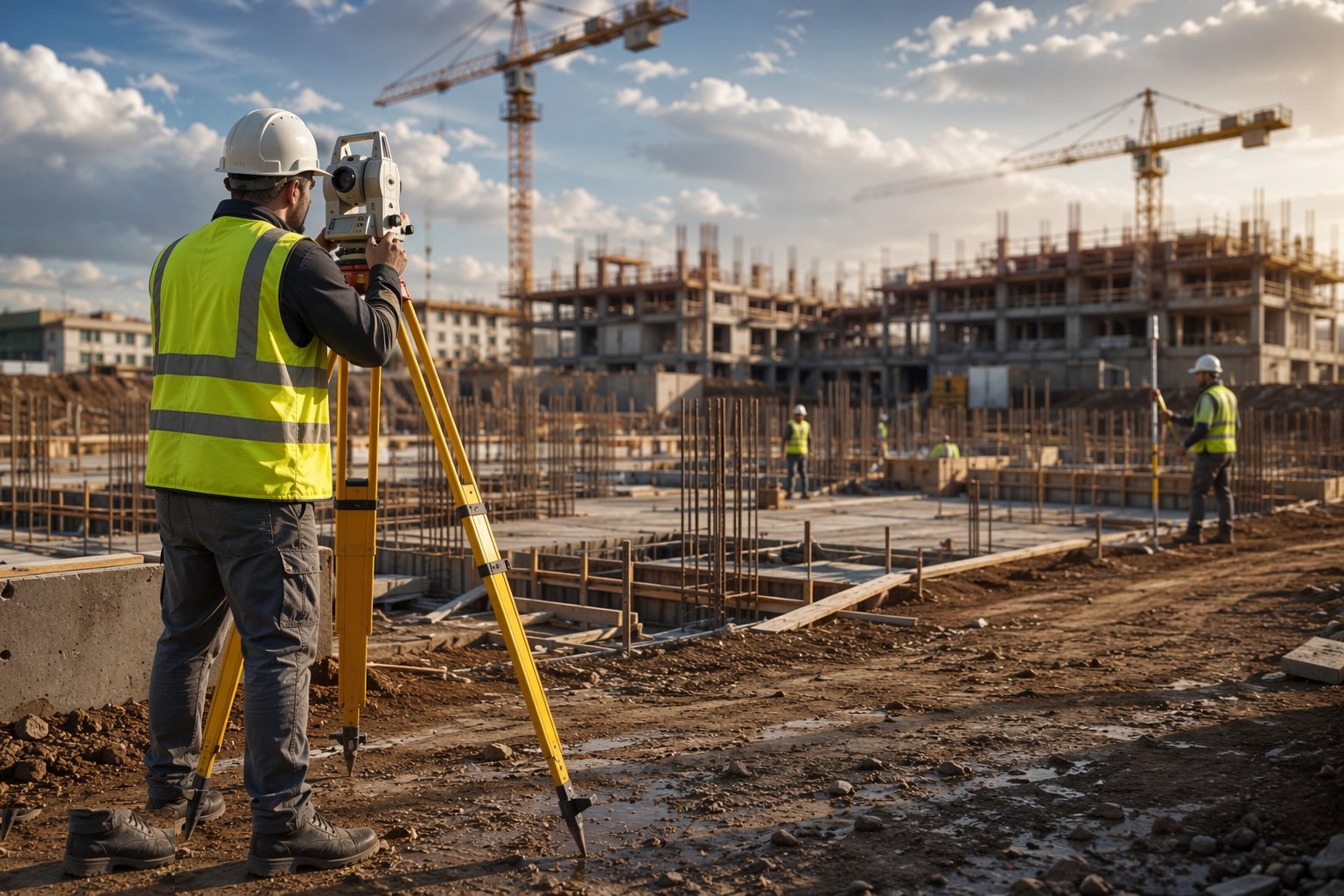
Primary control is re-verified on a fixed cycle - monthly is common - and immediately after any event that could disturb it: vibration, frost heave, a machine strike. Disturbed secondary points are reinstated only from primary control, never by eye or by interpolation between pegs. Every re-observation and revision is logged on the live control drawing.
What are the benefits of Total station (traverse) control?
- Millimetre-level accuracy for both setting out and as-built verification
- Independent of satellite coverage - works indoors, between structures, under canopy
- Full redundancy: closed traverses detect their own errors
- One robotic instrument and one operator can set out a whole frame
- Doubles as the as-built survey instrument at every hold point
- Proven, insurable method with a century of practice behind it
What are the limitations of Total station (traverse) control?
- Requires line of sight - stations must intersee or be re-established as the building grows
- Slower than GNSS for large open-area earthworks
- Control stations must be protected for the whole project - a struck station is a re-traverse
- Accuracy depends on operator discipline: heights, prisms, atmospheric settings
- Two-person checking adds programme time that presses get squeezed
- Instrument and calibration costs are significant, and certificates must stay in date
What is Total station (traverse) control best suited for?
What plant does Total station (traverse) control need?
- Total station - robotic preferred - with calibrated EDM
- Prisms, poles, tripods and tribrachs in matched, checked sets
- Steel pins, concrete, nails and paint for station construction
- Survey controller with coordinate-geometry software
- Precise level and invar staffs for the vertical network
- Fencing and protection materials for station security
How is Total station (traverse) control quality-checked?
- Traverse misclosure within tolerance and least-squares adjustment filed
- Level loops closed on independent benchmarks within tolerance
- Instrument and prism calibration certificates in date and on file
- Every set-out point checked from independent control before trade release
- Control re-verification log maintained - monthly and after disturbance events
- Signed check surveys filed at every hold point
More setting out & survey control methods
Next method
GNSS (RTK) control