The stack and emissions monitoring
A major structure in its own right, carrying monitoring equipment that is a condition of the operator's licence to run.
Last updated 2026-09-07
What is The stack and emissions monitoring?
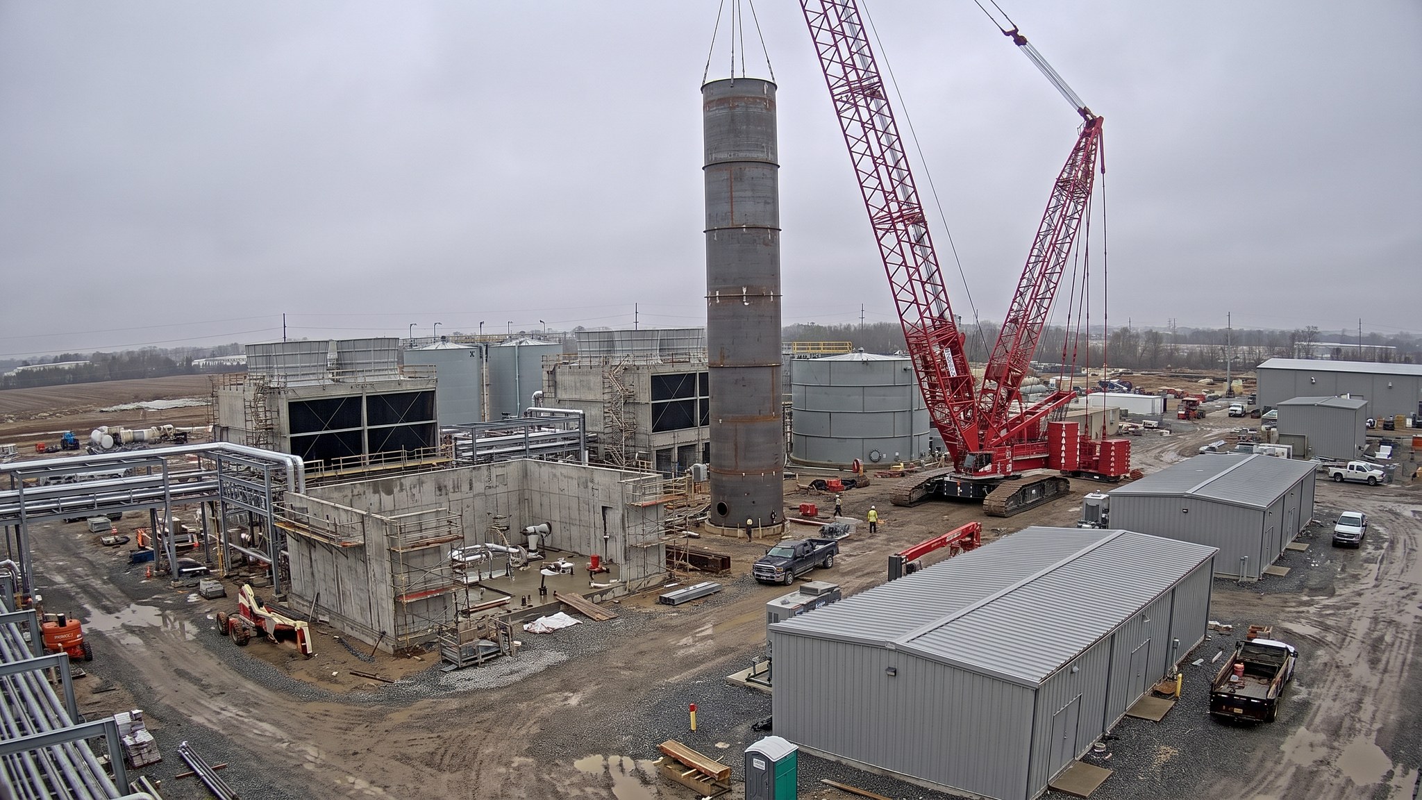
The stack is the last part of the gas path. It takes the cleaned flue gas from the plant and releases it at a height determined by dispersion modelling and agreed with the environmental regulator during consenting. Physically it is one of the largest structures on the site and usually the tallest, either a steel shell on its own foundation, a steel flue inside a concrete windshield, or a flue supported within the plant structure. Its height is not a design preference - it comes out of the consent, and it cannot be reduced afterwards to save money.
Inside and on the stack sits the monitoring equipment, and that equipment is a different order of importance from most instrumentation on the plant. The operator's environmental permit requires continuous monitoring of the flue gas, and the results are reported to the environmental regulator. If the monitoring is not working, the plant's position under its permit is affected regardless of what the plant is actually emitting. The monitoring installation is therefore designed, installed, calibrated and proved to a defined standard, with sampling positions, access platforms and reference measurement points all provided as the regulator requires.
For the construction team the stack is a tall structure job with an instrumentation job attached. It brings a large foundation, a significant erection sequence at height, aviation and navigation marking where required, lightning protection, earthing, internal lining or coating and permanent access for the life of the plant. The monitoring platform, its access, its power, its heating and its cable routes are all designed in rather than added later, because retrofitting access to a stack is difficult and expensive. Both parts have to be complete before the plant can run.
How does The stack and emissions monitoring work, step by step?
- 1
Step 1: Take the height and location from the consent
Stack height and position come from dispersion modelling carried out during consenting and agreed with the environmental regulator. They are fixed inputs to the project, not variables. Where aviation or navigation interests are affected, marking and lighting requirements are established at the same time. The team confirms the agreed height and position against the current layout at the start of detailed design, because layout changes made for other reasons can put the stack somewhere the modelling did not assume.
- 2
Step 2: Choose the stack form and design the foundation
The designer selects the form - a self-supporting steel shell, a steel flue within a concrete windshield, or a flue carried by the plant structure - based on height, the number of flues, the site conditions, maintenance access and cost. The foundation is designed for a tall, slender structure where wind governs, so overturning and dynamic behaviour matter more than weight. Ground investigation under the stack is treated seriously, and the holding-down arrangement is designed as a fatigue sensitive detail rather than as ordinary anchorage.
- 3
Step 3: Build the foundation and set the holding-down arrangement
The foundation is a substantial reinforced concrete element, commonly piled. Holding-down bolts or anchor assemblies are set on independent frames, surveyed before the pour and monitored during it, because the tolerance on them is tight and there is no adjustment available afterwards. Concrete is placed and cured under a thermal control plan where the pour is large. The completed foundation is surveyed and the as-built positions recorded and issued before erection begins.
- 4
Step 4: Erect the stack
Erection is either by lifting complete sections into place with a large crane, or by building up from the base using jacking or climbing methods where crane capacity or access will not allow full height lifts. The method is chosen early because it affects the design of the sections, the joints and the temporary works. Verticality is checked continuously as the structure rises, and temporary stability and wind limits during erection are designed and stated rather than judged. Working at height dominates the whole activity.
- 5
Step 5: Complete the lining, coating and protection systems
The internal surface is lined or coated to resist the flue gas condition it will see, and the external surface is protected against the weather. Lightning protection and earthing are installed and tested. Where aviation or navigation marking is required, painting and lighting are completed to the stated requirements, along with the power supply and the monitoring that keeps the lighting available. Drainage from the base of the flue is provided and routed to collection.
- 6
Step 6: Fit permanent access, platforms and lifting provision
The stack needs safe permanent access for the whole life of the plant, for monitoring equipment maintenance, for calibration work, for lighting maintenance and for inspection. Ladders or a lift, intermediate landings, the monitoring platform and any provision for lifting equipment up the structure are all designed and installed as part of the works. Rescue arrangements are considered as part of that design. These are much cheaper to build in than to add.
- 7
Step 7: Install the monitoring equipment and its sampling arrangements
Sampling points, the analysers and their housing, the heated lines, the power supplies, the cabling and the data links are installed to the design agreed for the permit. Sampling positions are located where the regulator requires them and the reference measurement points are provided alongside. The equipment is commonly supplier scope with the site providing the installation, the services and the environmental conditions the analysers need. Data routing to the plant systems and to reporting is set up and proved.
- 8
Step 8: Calibrate, prove and hand over to the operator
The monitoring system is calibrated and proved by specialists, with the arrangements and records that the operator's permit requires, and the reporting path is demonstrated end to end. This is done before the plant runs commercially, because the operator cannot run without working monitoring. The stack and the monitoring system are turned over as systems in the normal way, and from turnover the monitoring installation belongs to the operator and is maintained under their regime rather than touched by construction.
What are the benefits of The stack and emissions monitoring?
- Disperses flue gas at the height the consent requires, which is what makes the plant permissible
- Continuous monitoring gives the operator and the regulator a reliable record of plant performance
- A well designed stack needs little maintenance across a long service life
- Designed-in access and lifting provision make monitoring maintenance and calibration straightforward
- Lining and coating systems protect the structure against the flue gas condition for its design life
- Monitoring data integrates with plant control, giving operators early warning of process problems
What are the limitations of The stack and emissions monitoring?
- Height and position are fixed by the consent and cannot be adjusted for cost or layout convenience
- Tall slender structure with wind governing design, so foundations and erection are demanding
- Erection is entirely at height and highly weather sensitive
- Monitoring availability is a permit obligation, so equipment failure has consequences beyond the plant
- Access, platforms and services for monitoring are very expensive to retrofit if omitted
- Marking and lighting requirements can add ongoing maintenance obligations at height
What is The stack and emissions monitoring best suited for?
What plant does The stack and emissions monitoring need?
- Piling and heavy concrete plant for the foundation, with thermal control provision for large pours
- High capacity crawler cranes for section lifts, or jacking and climbing systems where lifting is not possible
- Precision survey equipment for verticality checks throughout erection
- Access equipment, hoists and fall protection systems for prolonged work at height
- Lining, coating and surface preparation equipment suitable for confined internal work
- Calibration and test equipment for earthing, lightning protection and the monitoring installation
How is The stack and emissions monitoring quality-checked?
- Agreed stack height and position reconfirmed against the current layout before detailed design
- Ground investigation and foundation design verified for a wind governed slender structure
- Holding-down assemblies set on independent frames, surveyed before the pour and recorded as-built
- Verticality checked and recorded at each stage of erection, with stated wind limits observed
- Earthing, lightning protection and marking lighting tested and recorded before handover
- Monitoring system calibrated, proved and its reporting path demonstrated before commercial operation