Conventional fired boiler
Fired directly rather than recovering exhaust heat, so it brings its own fuel handling, combustion air and flue gas systems with it.
Last updated 2026-09-07
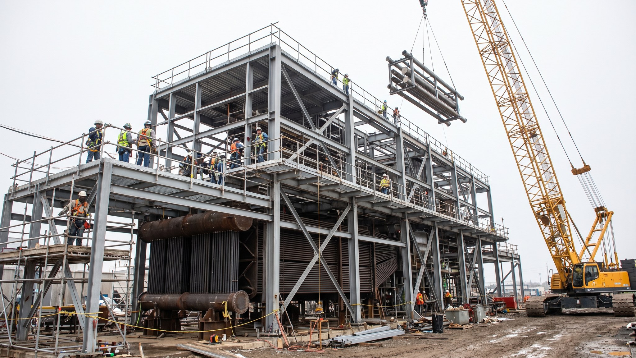
What is Conventional fired boiler?
A conventional fired boiler raises steam by burning fuel directly, rather than by recovering heat from a gas turbine exhaust. It is what a project uses where there is no gas turbine: a steam-only station, an industrial or process plant that needs steam as well as power, an energy recovery scheme, or a plant replacing or supplementing existing steam raising capacity. Structurally it is a tall unit with a furnace where combustion takes place, surrounded by water-cooled walls, with further heat transfer surface arranged in the gas path above and behind it before the gases leave for cleaning and the stack.
The important difference from a heat recovery unit is scope. A heat recovery unit is handed hot gas by somebody else. A fired boiler has to make it, which means the project also has to build everything that feeds and follows combustion: fuel reception, storage, preparation and delivery to the burners; combustion air supply, commonly preheated; the burners themselves and their control and protection systems; and the flue gas path with its cleaning equipment, fans and ducting. Each of those is a system in its own right with its own civils, its own electrical supply, its own controls and its own commissioning.
That breadth is what shapes the project. The boiler house is a tall building with heavy plant at high level, the fuel systems occupy a large area at the other end of the site, and the connection between them runs across the whole layout. Programme risk sits in the number of systems that all have to be complete before the boiler can be fired for the first time, not in any single one of them. Fuel and combustion systems are also where the most serious hazards on the plant live, so the burner and fuel scope is executed by the plant supplier and the operator under strict control and is never treated as ordinary installation work.
How does Conventional fired boiler work, step by step?
- 1
Step 1: Settle the fuel and the duty before anything else
What the boiler will burn, in what range of qualities, at what duty and with what availability governs the entire design. The designer, the plant supplier and the operator settle the fuel specification, the steam duty and the operating regime first, because burner selection, furnace sizing, surface arrangement, fuel handling and gas cleaning all follow from it. Consents from the environmental regulator are progressed in parallel, and the conditions attached to them commonly feed straight back into the plant arrangement.
- 2
Step 2: Build the boiler house structure and foundations
The boiler is tall and heavy, and much of its weight is carried from the top so that the pressure parts can expand downwards. That means a substantial steel structure with a heavy roof grid, on foundations designed for concentrated loads and for wind on a tall enclosure. The structure is erected and surveyed before the pressure parts arrive. Its accuracy matters because the hanging arrangement, the buckstays and the casing all attach to it and there is very little scope to adjust afterwards.
- 3
Step 3: Erect the furnace walls, drum and pressure parts
Water wall panels are lifted and hung from the roof steel, joined and sealed to form the furnace enclosure, and the drum and headers are set. Above and behind the furnace the further heat transfer surface is installed in the gas path. This is heavy lifting at height over an extended period, with a large volume of welding, heat treatment and examination. Expansion allowances, buckstay arrangements and seal boxes are installed exactly as the plant supplier designs them, because the whole enclosure has to be free to move as one.
- 4
Step 4: Install the burners and the combustion air system
Burners, wind boxes, igniters and flame detection are installed by or under the direct control of the plant supplier. The combustion air path is built alongside them: forced draught fans, ducting, dampers and, on most projects, an air preheater that recovers heat from the flue gas. Alignment, seals and damper operation are all proved before the system is handed on. The protection and interlock systems associated with the burners are supplier scope and are tested by the supplier as a system, not commissioned piecemeal.
- 5
Step 5: Build the fuel reception, storage and delivery systems
Fuel arrives, is stored, is prepared and is delivered to the burners at the condition the plant needs. What that involves depends entirely on the fuel, but it always brings its own civils, its own mechanical handling or piping, its own electrical supply and its own hazardous area classification. This work often runs on a separate front at the other end of the site with its own team. Gas fuel systems in particular are installed, tested and made ready by specialists under the operator's permit system and are not opened, purged or vented by anyone else.
- 6
Step 6: Complete the flue gas path, cleaning plant and stack
Downstream of the boiler the gas passes through the cleaning equipment the consent requires, then through the induced draught fans and ducting to the stack. The cleaning plant is commonly a package in its own right with substantial civils, and it has to be complete and proved before the boiler can run for any sustained period. Ducting is large, thin walled and easily distorted, so supports, stiffening and expansion joints are installed as designed and the whole path is checked for leakage before it goes into service.
- 7
Step 7: Complete the water, steam and auxiliary systems
Feedwater, condensate, blowdown, sampling, chemical dosing, drains and vents are all completed and connected, along with the electrical supplies, control systems and instrumentation that serve them. On a fired boiler the auxiliary list is long and it is where late scope tends to hide. Most teams manage it as a system-by-system completion register from an early stage, because the boiler cannot be fired until every supporting system that protects it is complete, tested and available.
- 8
Step 8: Clean, close up and turn over ready for firing
The pressure system and the gas path are cleaned, inspected and closed under formal records. Internal cleaning and steam blowing are specialist operations carried out by the plant supplier and the commissioning team under the operator's permit-to-work system, with the area cleared and controlled. From the point at which fuel is admitted to any part of the plant, permit-to-work discipline replaces normal site control entirely, and the boiler is turned over system by system to the commissioning team rather than handed over in one piece.
What are the benefits of Conventional fired boiler?
- Raises steam without needing a gas turbine, so it suits steam-only and process led schemes
- Can be designed around a range of fuels, including those a gas turbine cannot use
- Well established technology with a deep base of design, erection and operating experience
- Suits industrial sites where process steam is the primary product and power is secondary
- Can be added alongside existing steam raising plant to extend or replace capacity
- Operating regime is largely independent of any adjacent turbine, giving the operator flexibility
What are the limitations of Conventional fired boiler?
- Brings a large additional scope - fuel handling, combustion air, gas cleaning and stack - that a heat recovery unit does not
- Tall structure with heavy plant at high level, so erection is slow and crane intensive
- Fuel and combustion systems carry the most serious hazards on the plant and demand specialist control throughout
- Consent conditions from the environmental regulator can reshape the plant arrangement late
- Many separate systems must all be complete before first firing, which concentrates programme risk
- Gas cleaning plant adds substantial civils, cost and space at the downstream end
What is Conventional fired boiler best suited for?
What plant does Conventional fired boiler need?
- High capacity cranes for water wall panels, drums and surface modules lifted to full boiler height
- Strand jacks or lifting frames where panels are raised from within the structure
- Welding, heat treatment and non-destructive examination equipment deployed at height over a long period
- Mechanical handling or fuel piping installation plant for the fuel systems front
- Large diameter duct handling and support equipment for the gas path and cleaning plant
- Designed access scaffold, hoists and rescue arrangements for prolonged work at height
How is Conventional fired boiler quality-checked?
- Fuel specification, steam duty and operating regime agreed and frozen before the plant arrangement is fixed
- Environmental consent conditions tracked against the design, with any change fed back formally
- Structure surveyed for level and position before pressure parts are hung from it
- Welding, heat treatment and examination records compiled progressively for all pressure parts
- Gas path checked for leakage and duct supports and expansion joints verified before service
- Every supporting and protective system complete, tested and available on a completion register before first firing