Vertical gas path heat recovery unit
Exhaust travels upward through horizontal tube banks, trading extra support steel and working height for a much smaller footprint.
Last updated 2026-09-07
What is Vertical gas path heat recovery unit?
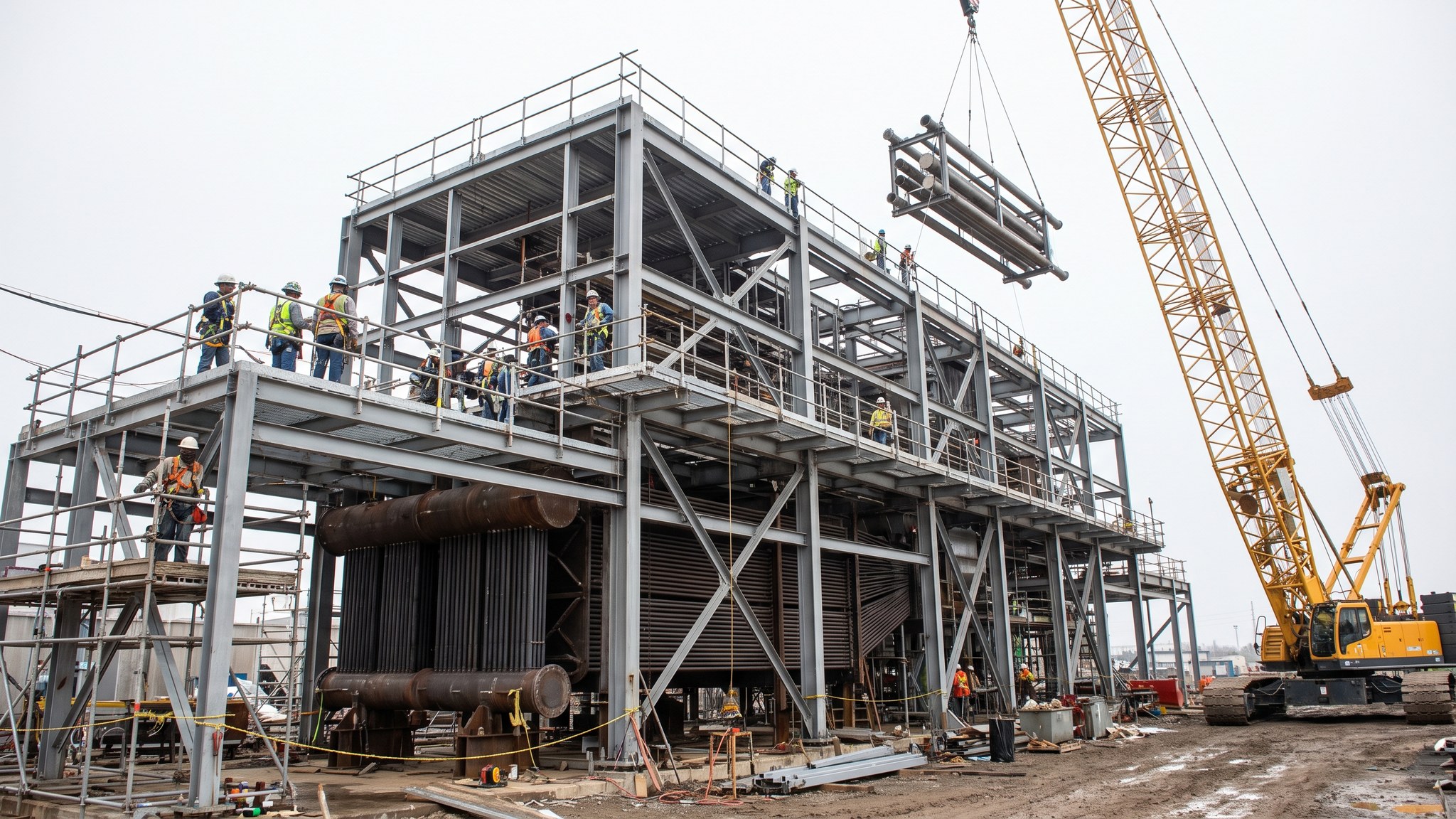
A vertical gas path heat recovery unit does the same job as a horizontal one but turns the gas path on end. The exhaust leaves the gas turbine, turns upward and travels vertically through the unit, passing across tube banks that are arranged horizontally and supported from a steel structure that surrounds them. The stack sits above or alongside the top of the unit. Thermally the two arrangements do the same work; the difference is entirely in shape, in how the surface is carried and in what that means for the site.
The reason a project chooses vertical is almost always land. Where the site is tight, where the plant is being added into an existing station, or where a boundary, a watercourse or an existing structure fixes the available strip, a vertical unit fits into a footprint a horizontal unit could not. That compactness also shortens the runs between the turbine, the unit and the steam turbine, which can simplify the pipe routing. On a constrained site those gains are decisive and the extra structure is simply accepted as the price.
The price is real. Horizontal tubes do not hang freely, so they need supports along their length, and those supports have to allow the tubes to move as they heat and cool while still carrying them. The surrounding steel is therefore heavier and more complex, and it has to carry the tube loads as well as the casing. Nearly all of the erection work moves up into the air, which means more time in crane hooks, more time on platforms and a slower, more weather-sensitive programme. Drainage from horizontal runs also needs designing rather than happening by gravity. None of it is exotic, but all of it costs time.
How does Vertical gas path heat recovery unit work, step by step?
- 1
Step 1: Confirm that the site really needs the vertical arrangement
The decision is a layout decision taken early, and it is taken jointly by the designer, the plant supplier and the operator. The team compares the footprint each arrangement needs against what the site can offer once roads, cranage, laydown, the stack position and future maintenance access are all allowed for. Vertical is chosen when the horizontal option genuinely will not fit or would force something worse elsewhere. It is not a preference to be revisited later, because the supporting structure, the foundations and the erection method all follow from it.
- 2
Step 2: Design and build the supporting structure first
On a vertical unit the steel structure is not just a stand - it carries the casing, the horizontal tube banks and the loads that come with them, and it commonly carries the stack too. Foundations are sized for a taller, more concentrated load with wind acting on a considerable height. The structure is erected and surveyed before the pressure parts arrive, and its accuracy governs everything that follows, because the banks have to slide into place between the supports at the levels the plant supplier has set.
- 3
Step 3: Plan the lifts before anything arrives on site
Almost every major component on a vertical unit goes up rather than along, so the lift plan is the erection plan. Crane type, position, radius and capacity are worked out against the heaviest component at the greatest height, and hardstandings are designed and proved for those loads. Weather limits are agreed in advance. On tight sites the crane position is often the single hardest problem to solve, and it is common for the erection sequence to be dictated by where a crane can physically stand.
- 4
Step 4: Set the casing and the inlet duct from the turbine
The casing is erected in sections up the structure and sealed as it goes. The inlet duct turns the exhaust from horizontal at the turbine to vertical at the unit, so it includes a substantial change of direction and it has to absorb movement between two structures that expand independently. Expansion joints, guides and sliding supports are installed to the supplier's cold settings, checked and recorded. Distribution of gas across the section is part of the supplier's design and the internal work is completed exactly as issued.
- 5
Step 5: Install the horizontal tube banks and their supports
Banks are lifted in and landed onto the supports built into the structure. Each bank has to be free to expand along its length while still being carried, so the supports, the slides and the spacers are installed exactly as designed and checked before the next bank goes above it. Seals between banks and casing are completed as work proceeds, since access closes off from below. Transport damage is looked for on every bank before it is lifted, because a damaged bank at height is a very expensive discovery.
- 6
Step 6: Complete drums, headers, interconnecting pipework and drainage
Drums are lifted and set, headers connected and the interconnecting pipework routed through the structure. Drainage needs more thought than on a horizontal unit because the tube runs are horizontal: every low point has to be drained deliberately, and the drain routing is part of the supplier's design rather than something arranged on site. Welding, heat treatment and examination follow the approved procedures, and supports and hangers are installed and locked at their cold settings.
- 7
Step 7: Insulate, seal and complete access at height
Insulation, casing seals and cladding are completed up the full height of the unit, along with the permanent platforms, ladders and stairs that maintenance will use. Because so much of this work is at height and on the outside of the structure, it is exposed to weather and it is often the activity that slips. Teams that plan the access scaffold or the mast climbers as a designed temporary works item, rather than improvising, keep the finishing trades moving through the winter.
- 8
Step 8: Clean, close up and turn over system by system
The gas path and the pressure system are cleaned, inspected and closed under formal records. Internal cleaning and steam blowing are specialist operations planned and executed by the plant supplier and the commissioning team under the operator's permit-to-work system, with exclusion zones set and other work stopped in the area. Turnover to commissioning is done system by system, each with completed records, and the commissioning team is on site working alongside erection long before the unit is finished.
What are the benefits of Vertical gas path heat recovery unit?
- Fits into a much smaller footprint than a horizontal unit of the same duty
- Suits constrained sites, additions to existing stations and layouts fixed by a boundary or a watercourse
- Shorter runs between the gas turbine, the unit and the steam turbine can simplify pipe routing
- Frees ground area for laydown, roads and maintenance access that a long unit would consume
- The stack can often be integrated with or carried by the same structure
- Compact arrangement can reduce the length of gas path ducting and its associated losses
What are the limitations of Vertical gas path heat recovery unit?
- Horizontal tubes need supports along their length, so the steel structure is heavier and more complex
- Nearly all erection work is at height, which slows the programme and increases weather sensitivity
- Crane capacity and crane position become the governing constraint on the whole erection sequence
- Drainage of horizontal tube runs has to be designed deliberately rather than relying on gravity
- Working at height increases the temporary works, access and edge protection burden throughout
- Fewer contractors have built one, so experienced erection resource can be harder to secure
What is Vertical gas path heat recovery unit best suited for?
What plant does Vertical gas path heat recovery unit need?
- High capacity crawler or tower cranes able to reach full unit height at the required radius
- Designed and proven crane hardstandings, with ground improvement where needed
- Mast climbers, hoists or designed access scaffold for insulation and cladding at height
- Welding, heat treatment and non-destructive examination equipment usable at height
- Survey equipment for verticality and level checks up the full structure
- Rescue and emergency arrangements suited to work at height inside and outside the casing
How is Vertical gas path heat recovery unit quality-checked?
- Layout decision recorded with the designer, the plant supplier and the operator before the structure is designed
- Steel structure surveyed for level, plumb and support positions before any pressure part is lifted
- Lift plans reviewed and approved as designed temporary works, with weather limits stated
- Tube bank supports, slides and spacers installed and checked bank by bank before the next is placed
- Every low point in the pressure system confirmed drained in accordance with the supplier's design
- System turnover packages completed, with cleanliness and closure records signed before commissioning starts