Horizontal gas path heat recovery unit
The common large arrangement - exhaust travels horizontally through vertically hung tube banks, giving a long footprint and a straightforward erection.
Last updated 2026-09-07
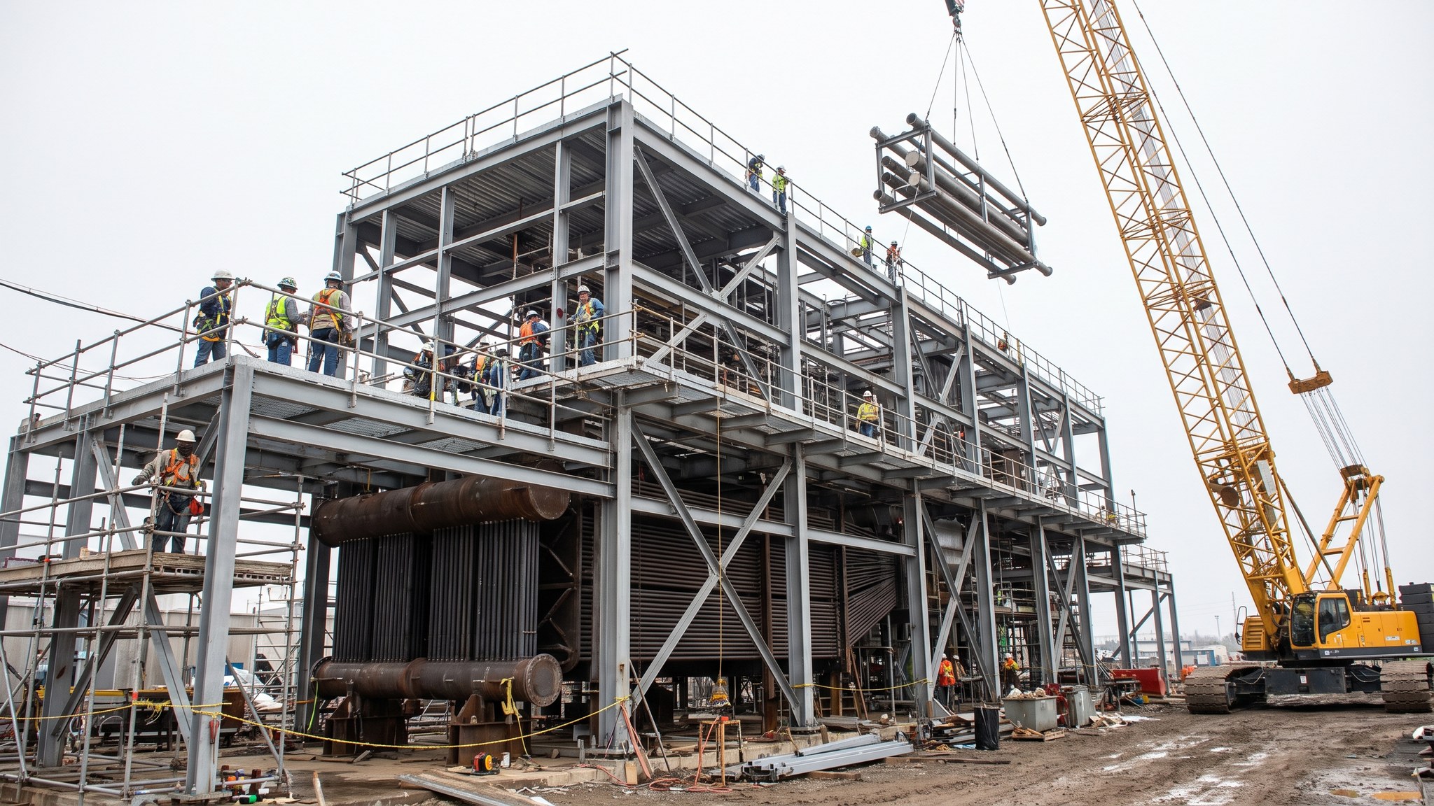
What is Horizontal gas path heat recovery unit?
A heat recovery unit sits behind a gas turbine and takes the heat out of the turbine exhaust to raise steam for a steam turbine. In the horizontal gas path arrangement the exhaust leaves the turbine, turns through a transition duct and then travels horizontally along the length of a large rectangular casing. Inside that casing the heat transfer surface is arranged as tube banks hung vertically from headers carried in the roof, so the gas passes across the tubes as it moves along the unit. On most large combined cycle projects this is the arrangement chosen, and it is what most contractors and most erection teams have built before.
The reasons it dominates are practical rather than thermodynamic. Because the tubes hang from the top they are free to expand downwards under their own weight, which keeps the support arrangement simple and avoids a lot of restraint detailing. Condensate runs down the tubes to drains at the bottom rather than having to be collected along horizontal runs. The casing itself is a long box that the plant supplier can break into transportable sections, and much of the work sits at a moderate height rather than at the top of a tall structure. The result is a unit that is comparatively simple to build, to inspect and later to maintain.
What it costs is land. A horizontal unit is long, and the gas path, the duct from the turbine and the stack at the far end together take up a considerable strip of the site. That length drives the foundations, the pipe racks, the access roads and the crane positions, and it has to be settled early because nothing about the layout can move once the plant supplier has issued the unit arrangement. The unit is a supplier-designed package that the contractor erects, so the interface between supplier scope and site scope is defined at contract stage and managed continuously through the build.
How does Horizontal gas path heat recovery unit work, step by step?
- 1
Step 1: Fix the arrangement and the interfaces with the plant supplier
The heat recovery unit is designed by the plant supplier around the gas turbine it serves, so the site team receives an arrangement rather than developing one. The early work is to fix the interfaces: the position and level of the turbine exhaust, the centreline of the gas path, the stack location, the loads that arrive at each support point, the pipework connection points and the split between shop-assembled and site-assembled work. On most projects the erection method is agreed at the same time, because it determines how the supplier will split the unit for transport.
- 2
Step 2: Build the foundations and the supporting steelwork
The unit is heavy and it is long, so the foundation layout follows its length. Piles or pads are installed under the casing supports, the duct supports and the stack, and the supporting steelwork is erected on them to the levels the supplier requires. Setting-out accuracy matters because the casing sections have to land on their supports and line through with each other and with the turbine exhaust. Survey control is established before erection begins and re-checked as the steelwork rises.
- 3
Step 3: Erect the casing and the gas path ducting
The casing arrives as sections, commonly with the tube banks already fitted, and is landed onto the steelwork in sequence from the turbine end. Sections are aligned, levelled, seam welded or bolted as the supplier specifies, and then the transition duct from the turbine is fitted. The duct is a substantial fabrication in its own right and it has to accommodate movement between two structures that expand differently. Expansion joints, guides and sliding supports are all set to the supplier's cold settings and recorded.
- 4
Step 4: Install the tube banks and the hanging arrangement
Where banks are installed separately they are lifted in from above and hung from the header steel, then aligned so that the tubes sit correctly in the gas path with the clearances the supplier states. The hanging arrangement, the tube spacers and the seals between banks all get careful attention, because gas that finds a way past the surface instead of through it costs output for the life of the plant. Every bank is inspected for transport damage before it goes in, since access afterwards is limited.
- 5
Step 5: Set the drums, headers and interconnecting pipework
Steam drums are lifted and set on their saddles, headers are connected and the interconnecting pipework between the pressure sections is routed, welded and supported. This is the most weld-intensive part of the unit and it is where the programme is usually decided. Welding is carried out to approved procedures by qualified welders, with heat treatment and non-destructive examination applied as the specification requires. Pipe supports, spring hangers and guides are installed and locked at their cold settings.
- 6
Step 6: Install insulation, casing seals and access
The gas path is lined and insulated to the supplier's design, seals are completed at every penetration and casing joint, and the internal and external access arrangements are fitted. Insulation is not a finishing trade on a heat recovery unit - it is part of the design, and gaps in it show up later as hot spots on the casing and as lost output. Doors, hatches, walkways and platforms are completed so that the unit can be entered safely for inspection.
- 7
Step 7: Fit valves, instruments, drains and vents
Valves, instrument connections, drains and vents are installed and the small-bore pipework is completed and supported. Every instrument tapping is checked against the plant supplier's schedule, because a missing or mislocated tapping is found at commissioning when the system is already closed up. Drains and vents are routed to the collection systems the design provides. Safety-related fittings are installed by the plant supplier or under the supplier's direct supervision and are left set and sealed by them.
- 8
Step 8: Clean, inspect and hand the unit over system by system
Before the unit goes anywhere near operation it is cleaned internally, inspected and closed up under a formal record. The pressure system is then subject to a series of specialist operations - internal cleaning and steam blowing among them - which are planned and executed by the plant supplier and the commissioning team under the operator's permit-to-work system, with the surrounding area controlled and construction work suspended. Site erection scope is turned over system by system rather than as a single handover, each with its own completed records.
What are the benefits of Horizontal gas path heat recovery unit?
- The arrangement most contractors and erection teams have built before, so methods and risks are well understood
- Vertically hung tubes expand downwards freely, which simplifies supports and restraint detailing
- Condensate drains down the tubes by gravity to collection points at the bottom
- Much of the erection work sits at moderate height rather than at the top of a tall structure
- The casing splits naturally into transportable sections that arrive with surface already fitted
- Good internal access for inspection and cleaning through the life of the plant
What are the limitations of Horizontal gas path heat recovery unit?
- Needs a long footprint, which constrains the whole site layout and cannot be changed later
- Foundations, pipe racks, roads and crane positions all follow that length and multiply with it
- The transition duct from the turbine is a demanding fabrication that has to absorb differential movement
- Heavy lifts along the full length of the unit tie up cranage for an extended period
- The unit is a supplier package, so site progress depends on supplier deliveries arriving in erection sequence
- Weld volume in the interconnecting pipework commonly sets the critical path
What is Horizontal gas path heat recovery unit best suited for?
What plant does Horizontal gas path heat recovery unit need?
- Crawler cranes sized for casing sections, drums and tube banks, with prepared and proven crane hardstandings
- Transport and jacking equipment for moving heavy sections along the length of the unit
- Welding plant, heat treatment equipment and non-destructive examination facilities for the pressure parts
- Survey equipment and established control for setting out supports along a long structure
- Access towers, mobile platforms and edge protection for casing, insulation and duct work
- Temporary power, lighting and ventilation for internal work inside the gas path
How is Horizontal gas path heat recovery unit quality-checked?
- Interfaces with the gas turbine, the stack and the pipework agreed and frozen with the plant supplier before erection
- Support levels and centrelines surveyed and recorded before and after each casing section is landed
- Welder qualifications, weld procedures, heat treatment records and examination results compiled as work proceeds
- Expansion joints, guides and spring hangers set to cold settings and the settings recorded
- Internal cleanliness inspected and formally recorded before the gas path and pressure parts are closed
- System turnover packages completed and accepted by the commissioning team before any system is energised
More boiler & hrsg erection methods
Next method
Vertical gas path heat recovery unit