Visual approach slope indicators
Light units beside the runway that show a pilot the approach path visually - set and checked by specialists, never on site.
Last updated 2026-09-05
What is Visual approach slope indicators?
A visual approach slope indicator is a set of light units positioned beside the runway that gives an approaching pilot a visual indication of whether the aircraft is on, above or below the intended approach path. The pilot reads the indication directly from the appearance of the lights, so what those units show, and where they show it, is the whole function. The system is simple to describe and unforgiving in execution, because its usefulness depends entirely on the units being in exactly the right place and set to exactly the right alignment.
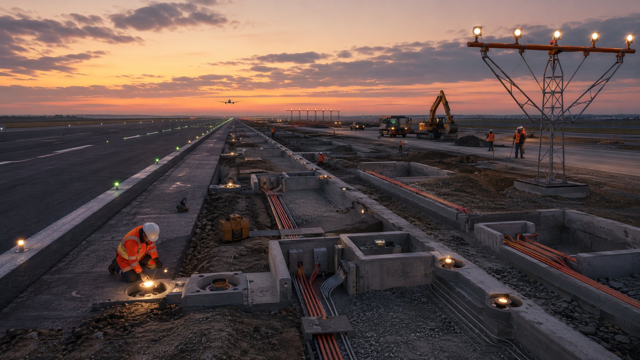
For that reason the siting and the setting of the units belong to the designer, the airport operator, the aviation regulator and the appointed specialists. The position of each unit and the alignment it is set to are determined from the runway, the approach and the operations the airport supports, and they are not matters a contractor establishes, checks or adjusts. The construction scope is the civils around them: foundations, bases, frangible mountings, ducting, cabling containment, access and the ground conditions the units sit on. Like other elevated airfield fittings in areas an aircraft could reach, the units are mounted frangibly.
Two constraints follow the installation for life. The first is stability: the units must not move. Ground movement, settlement of a foundation, a vehicle strike or someone leaning a ladder against a unit all put the alignment out, and an alignment that is out is worse than no system at all. Foundations are designed for the ground rather than assumed, and the units are protected from vehicles and from casual contact. The second is obstruction: nothing may be allowed to grow, be parked or be built where it blocks the view of the units from the approach. After installation and after any disturbance, the units are set by the specialists and flight-checked before the operator returns them to service.
How does Visual approach slope indicators work, step by step?
- 1
Step 1: Siting and setting are determined by the specialists
Where the units go and what they are set to are decided by the designer, the airport operator and the aviation regulator, with the appointed specialists carrying out the setting. Those decisions come from the runway, the approach and the aircraft that use it. The contractor receives positions and builds to them. Nothing about the alignment is adjusted, checked or interpreted by construction staff at any point, and any conflict on site is referred back rather than resolved locally.
- 2
Step 2: Design foundations for stability, not just for load
The governing requirement for the foundations is that the units do not move over time. That means foundations designed for the actual ground conditions - which beside a runway are often made ground, fill or soft alluvium - rather than a standard detail. Settlement, heave, frost action and ground water are all considered. On most projects the foundations are the single most important part of the construction scope, because a unit that settles has lost its setting and the whole installation has to be re-set and re-checked.
- 3
Step 3: Install bases and frangible mountings correctly
Each unit sits on a base carrying a frangible mounting arrangement, installed with the manufacturer's components and tightening. As with all elevated airfield fittings, substituting a fixing, adding a bracket or over-tightening defeats the frangibility and is a defect. The base is set level and square as the manufacturer requires so the unit can be set within its adjustment range. Bases are surveyed as installed and the records kept.
- 4
Step 4: Install ducting, cabling and connect under permit
Ducts, draw ropes, chambers and containment are installed by the civils contractor, and the connection into the series lighting circuit is made by qualified airfield lighting specialists under the airport operator's permit-to-work, with the circuit isolated by the operator. Terminations and seals are made to the manufacturer's requirements. As with all series circuitry, this is high-voltage work and nobody outside the authorised specialists goes near it.
- 5
Step 5: Specialists set and calibrate the units
Once installed, the units are set and calibrated by the appointed specialists using their own equipment and procedures. This is a precise operation and it is theirs entirely. The construction team's job during it is to keep the area clear, provide access and then leave the units alone. After setting, the units are protected so that nothing on site disturbs them before the check flight.
- 6
Step 6: Flight check before return to service
The installation is checked from the air, with the check arranged by the airport operator and assessed against the aviation regulator's requirements. The units are not usable until the operator and the regulator accept the result and return them to service. Re-checking is required after any disturbance, after works nearby that could have moved a foundation, and on the operator's routine cycle. Construction completion and operational acceptance are different events, and the second is not the contractor's to declare.
- 7
Step 7: Protect the units and the view of them
The units are protected from vehicle strike, from ground equipment and from people using them as something to lean on. Equally important, the view of the units from the approach is kept clear: vegetation, parked equipment, stockpiles, temporary structures and site hoardings all have to be kept out of the way, and the operator states where. During construction this is a daily discipline; after handover it becomes part of the operator's routine airfield inspection.
- 8
Step 8: Record everything the next team will need
Foundation details, base positions, frangible component types, cable routes and the date of the last setting and check are all recorded and handed to the operator. When a unit is struck or a foundation is suspected of moving, the operator needs to know what was installed and when it was last checked, without excavating to find out. On most projects these records are compiled as the work proceeds, because after handover the installation is inspected far more often than it is opened up.
What are the benefits of Visual approach slope indicators?
- Gives a pilot a direct visual indication of the approach path without airborne equipment
- Simple, robust light units with mature specialist support and replaceable components
- Independent of the aircraft fit, so it benefits every operator using the runway
- Frangible mounting means a strike damages the unit rather than the aircraft
- Civils and foundations are conventional construction within a general contractor's scope
- Once set and checked, the installation is stable and cheap to maintain
What are the limitations of Visual approach slope indicators?
- Performance depends entirely on position and setting, neither of which is a site matter
- Any movement of a foundation invalidates the setting and forces re-setting and re-checking
- Requires flight checking before return to service, which has to be arranged and scheduled
- The view of the units from the approach must be kept permanently clear of obstruction and vegetation
- Vulnerable to vehicle strike and casual contact in a busy airside environment
- Ground beside runways is often poor, so foundations may be significantly more involved than expected
What is Visual approach slope indicators best suited for?
What plant does Visual approach slope indicators need?
- Foundation plant sized to the ground conditions, which beside a runway are often poor
- Frangible mountings and manufacturer-specified fixings held as controlled components
- Ducting, draw ropes, chambers and containment for the cabling
- Survey equipment for positioning and for recording bases as installed
- Protective barriers or bollards where the operator requires strike protection
- Appointed specialists with their own setting equipment, and a flight check arranged by the operator
How is Visual approach slope indicators quality-checked?
- Positions issued by the designer, operator and regulator, and built to without variation
- Foundations designed for the actual ground conditions with stability as the governing requirement
- Frangible mountings installed with the correct components and tightening, and inspected specifically
- Cable connection made, tested and proved by qualified specialists under the operator's permit-to-work
- Setting and calibration carried out by the appointed specialists, with the units left undisturbed afterwards
- Flight check completed and return to service authorised by the operator, with all records handed over