Space frames and shell roofs
Three-dimensional grids and curved shells, mostly assembled on the ground and lifted into place as complete pieces.
Last updated 2026-09-05
What is Space frames and shell roofs?
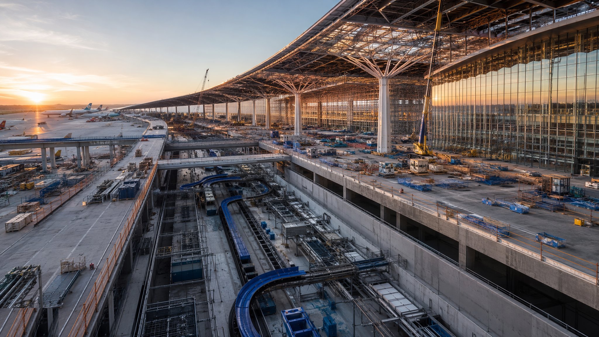
A space frame spreads load in two directions rather than one. Instead of a series of parallel trusses each carrying its own strip of roof, a space frame is a three-dimensional grid of members and nodes acting as a single plate, so a load applied anywhere is shared by members all around it. That makes it efficient over large square or irregular areas, tolerant of columns being placed where the building wants them rather than on a strict grid, and highly redundant, since load finds another path when one member is overloaded. A shell roof achieves something similar by curvature, carrying load largely as forces within the surface of the shell rather than by bending. Both are chosen in terminals where the plan is wide in both directions and the architecture wants a light, repetitive, visible structure.
The characteristic of both forms is repetition. A space frame is built from a limited number of standard members and proprietary or bespoke node connectors, made in large quantities to tight tolerances. That repetition is what makes them economic, and it is also what makes them unforgiving: an error repeated across hundreds of identical components is an error everywhere. Dimensional control in fabrication is therefore the single most important quality activity on this kind of roof, and a trial assembly is normal rather than exceptional. The designer sets the grid module, the member sizes, the node type and the support arrangement for the roof in question.
On site the defining technique is ground assembly followed by lifting. Because a space frame is a repetitive grid of relatively small pieces, most of it can be bolted together at ground level on a prepared, level and surveyed assembly area, with the roof covering, services, lighting and even cladding sometimes fitted before the structure ever leaves the ground. The completed section is then raised as a single unit, by crane, by strand jacks climbing on temporary towers, or by jacking on the permanent columns. That reverses the usual balance of construction risk: nearly all the work happens safely at ground level and the dangerous part is compressed into one carefully engineered operation. The lift itself becomes the critical event of the project, planned in detail, rehearsed, monitored and executed once.
How does Space frames and shell roofs work, step by step?
- 1
Step 1: Set the geometry, the module and the support conditions
The designer fixes the grid module, the depth of the frame or the curvature of the shell, the member and node types, and where and how the roof is supported. Support conditions matter more here than in a simple beam roof, because a space frame that is restrained differently from the way it was analysed will attract forces it was not designed for. Movement joints, sliding bearings and the way the roof meets the supporting structure are all settled at this stage.
- 2
Step 2: Fabricate to tight tolerance and prove the fit
Members and nodes are fabricated in quantity with dimensional checks on a sampling regime that reflects how many identical pieces there are. A trial assembly of a representative area, or of the whole roof where the geometry warrants it, is carried out in the fabrication works. Finding a systematic error in the yard costs a batch of components. Finding it on site with a crane booked costs the programme.
- 3
Step 3: Prepare and survey the assembly area
A large, level, well-drained and surveyed area is set aside on site for assembly, with access for deliveries and for the lifting plant. The area is set out precisely, because the geometry of the finished roof is established here and cannot be corrected once the frame is up. Temporary supports and packers under the assembly are levelled and monitored, and the ground beneath is treated as a working platform in its own right, designed for the assembly and lifting loads.
- 4
Step 4: Assemble the frame at ground level
The grid is built up from the set-out, module by module, with connections made and checked at ground level where inspection is easy and safe. Geometry is surveyed continuously as the assembly grows, because small errors accumulate across a repetitive grid. The assembly sequence and any temporary stiffening needed while the frame is incomplete come from the temporary works design, since a partially built space frame does not have the redundancy the finished one does.
- 5
Step 5: Fit out the roof before it leaves the ground
Wherever the lift capacity allows, roof decking, covering, insulation, lighting, sprinkler pipework, cable containment and even glazing are installed while the frame is still at ground level. This is the main commercial and safety argument for the technique - work done at ground level is faster, safer and better than the same work done from a mobile platform at high level. What can be added is limited by the lifting capacity and by how the added weight and stiffness change the frame during the lift, which the designer checks.
- 6
Step 6: Engineer the lift as a designed operation
The lift is designed, not improvised. Lifting points are located where the designer says the frame can take them, the frame is checked for the forces it sees while hanging or being jacked, and any temporary stiffening for the lift condition is installed. The strand jack or crane arrangement, the synchronisation between lifting points, the permitted differential between them, the wind limits and the abort criteria are all fixed in writing beforehand, and the sequence is walked through with everyone involved.
- 7
Step 7: Lift, monitor and land onto the permanent supports
The frame is raised in a controlled, monitored operation, with the load at each lifting point, the level differences across the frame and the movement of the supporting structure all watched in real time against the limits set. Progress stops at planned hold points for checks. On landing, the frame is secured to its permanent supports in the sequence the designer specified, which controls how the roof takes up its final geometry and how the forces redistribute.
- 8
Step 8: Release the temporary works and verify the finished geometry
Lifting equipment and temporary towers are released in a controlled sequence, with the frame surveyed as load transfers to the permanent supports. Deflections are compared with the designer's predictions, which is the real confirmation that the roof is behaving as analysed. Remaining perimeter work, cladding interfaces and services connections are completed, and the as-built geometry and the monitoring records are handed over.
What are the benefits of Space frames and shell roofs?
- Spreads load in two directions, so it suits wide, square or irregular plan areas
- Highly redundant, with alternative load paths if a member is overloaded
- Built from repetitive standard components, which is economic in fabrication
- Most of the work, including roof fit-out, happens safely at ground level
- Very short time spent working at height compared with piece-by-piece erection
- Light, visually open structure that suits the architectural intent in terminal concourses
What are the limitations of Space frames and shell roofs?
- The lift is a single high-consequence operation with little room for improvisation
- Needs a large, level assembly area, which is scarce on a constrained airport site
- Repetitive components mean a systematic fabrication error is repeated everywhere
- Node connections are specialised and sensitive to fabrication tolerance
- Lifting capacity limits how much fit-out can be added before the roof leaves the ground
- Local repairs and later alterations are harder in a redundant grid than in a simple frame
What is Space frames and shell roofs best suited for?
What plant does Space frames and shell roofs need?
- Strand jacks with temporary lifting towers, or cranes sized for the assembled unit
- Synchronised lifting control system with real time load and level monitoring
- Assembly trestles, packers and levelling equipment for the ground assembly area
- Bolting and torque equipment matched to the node connection type
- Mobile elevating work platforms for perimeter and connection work
- Precision survey instruments for geometry control and deflection monitoring
How is Space frames and shell roofs quality-checked?
- Fabrication dimensional control on a sampling regime scaled to the number of identical parts
- Trial assembly in the works before delivery to site
- Assembly area set out and surveyed, with geometry checked continuously as the frame grows
- Connection tightening checked and recorded module by module at ground level
- Lift plan, lifting point design, synchronisation limits, wind limits and abort criteria agreed in writing
- Deflections surveyed on landing and on release, and compared with the designer's predictions