Composite reconstruction
Asphalt over concrete, or concrete over asphalt, used to rebuild a worn-out pavement without losing the levels the airfield already has.
Last updated 2026-09-05
What is Composite reconstruction?
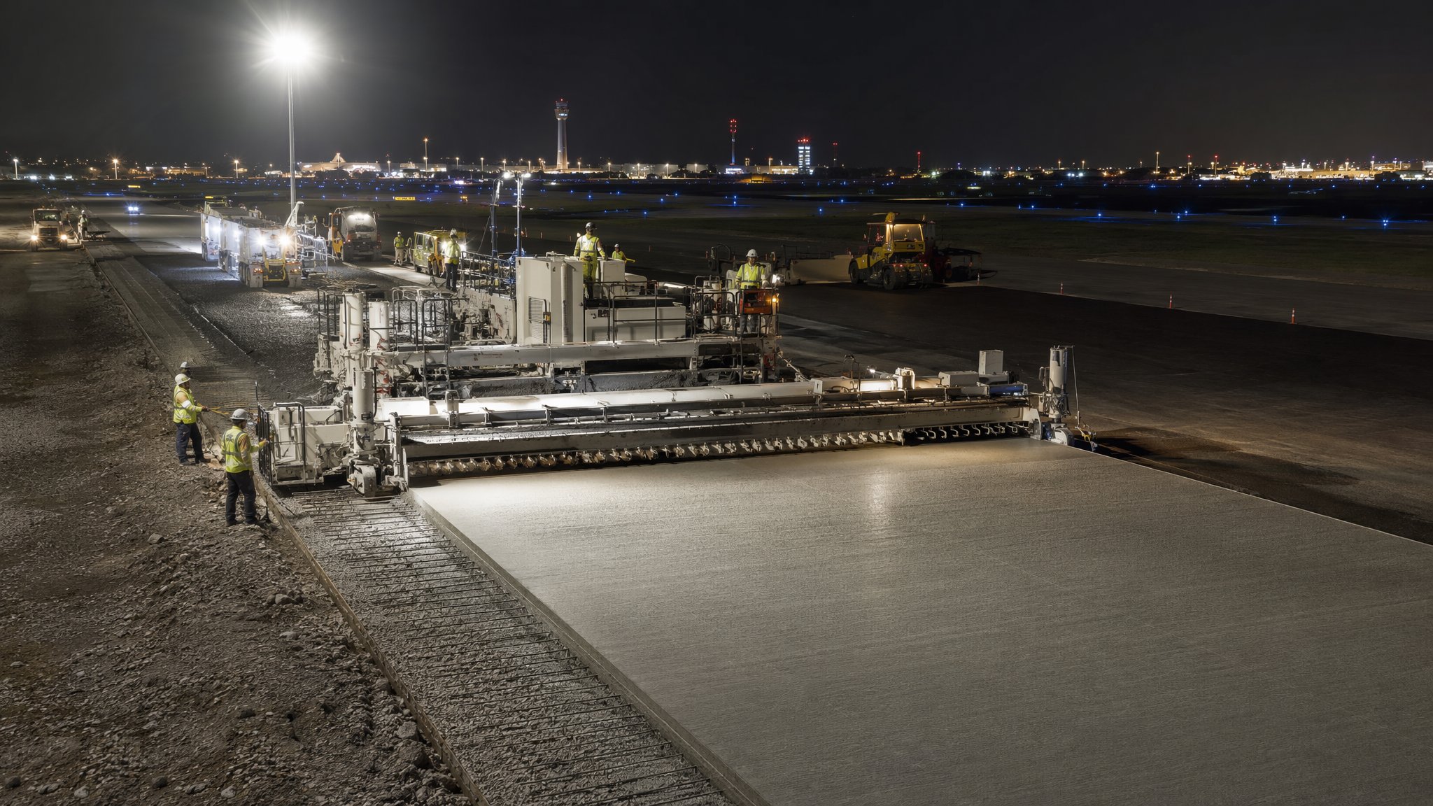
Composite reconstruction means rebuilding an existing pavement as a combination of rigid and flexible construction, usually a bound asphalt surfacing over a concrete base, and sometimes concrete laid over an existing asphalt pavement. It is rarely the first choice for a new pavement. It is very often the right answer for an old one. An airfield that has been in service for decades has a pavement that is worn out at the top but still structurally useful lower down, sitting between drainage, inset lighting, buildings and taxiway connections that all fix the finished level within a very narrow band. Composite construction lets the team reuse the sound part of the old pavement, replace the part that has failed, and come back out at the same level.
The level constraint is what usually drives the choice. Raising a runway or apron surface has consequences that spread far beyond the paving: drainage falls reverse, gully and manhole covers need rebuilding, inset light fittings need raising, thresholds and taxiway junctions need tie-ins, and the transition back to adjacent unreconstructed pavement has to be ramped somewhere. Digging the whole thing out and starting again removes those problems but costs a great deal of programme, and programme on a live airfield is measured in closures the operator would rather sell to airlines. Composite reconstruction is the compromise: take out the depth you must, put back a stronger build-up in the same depth, keep the levels.
The recurring problem, and the one that decides whether a composite pavement is a success in ten years, is reflective cracking. A concrete layer beneath moves at its joints as it expands and contracts, and that movement concentrates strain in the bound layer above until a crack works its way up to the surface, tracing the joint pattern of the layer below. Water then gets in and the deterioration accelerates. There are well-established ways of managing it: increasing the thickness of the overlay, using modified or more flexible mixtures, cracking and seating the old concrete so that its slabs become smaller and move less at any one place, or introducing an interlayer or reinforcement to spread the strain. All of these reduce the problem rather than eliminate it, and the designer chooses among them for the pavement in front of them.
How does Composite reconstruction work, step by step?
- 1
Step 1: Investigate what is actually there
Composite reconstruction begins with finding out what the existing pavement is made of, because the record drawings for an airfield built over decades are usually incomplete. Cores are taken through the pavement, trial pits are dug, layer thicknesses and materials are logged, and the condition of each layer is assessed. Non-destructive testing across the area shows where the pavement is stiff and where it is not. The result is a map of what can be kept and what has to go, and that map, not the original design intent, is what the reconstruction is built on.
- 2
Step 2: Fix the level constraints before the build-up
The team surveys everything that fixes the finished level: drainage covers, inset lighting, existing falls, tie-ins to adjacent pavement, thresholds and building thresholds. Those constraints define the depth available. The pavement engineer then designs a build-up that fits inside that depth and gives the strength required. Where the two cannot be reconciled, the choice is to raise the surface and accept the knock-on work, or to go deeper and accept the programme. That decision is taken early and by the designer and the airport operator together, not discovered on site.
- 3
Step 3: Plane or break out to the agreed horizon
The failed material is removed to the depth the design sets. Where the old surfacing is asphalt over sound concrete, that is planing. Where the concrete itself is failing, bays are broken out and replaced or the whole slab layer is treated. Arisings are removed from the airfield or stockpiled for reuse where the specification allows. The exposed surface is swept and inspected, and areas that turn out to be worse than the investigation suggested are recorded and referred back to the designer rather than covered up.
- 4
Step 4: Repair and prepare the retained layer
The layer being kept has to be sound before anything goes on top of it. Cracks are treated, spalled joints are repaired, voids beneath slabs are filled, and drainage is proven. Where the design calls for cracking and seating, the old concrete is broken into smaller pieces in a controlled way and rolled to seat them firmly on the ground beneath, which reduces how much any one joint can move. That work is deliberate and controlled, and its extent is set by the designer for the specific pavement.
- 5
Step 5: Install the crack relief measures the design calls for
Whatever the designer has chosen to manage reflective cracking is installed at this point: a stress-absorbing interlayer, a reinforcing grid, a thicker or more flexible lower bound layer, or a combination. Continuity matters more than anything here. An interlayer that stops short at the edges, is laid over a dirty surface, or is lapped incorrectly leaves exactly the discontinuity the crack will find. Installation is inspected as it goes because none of it is visible once the surfacing is laid.
- 6
Step 6: Lay the new bound layers to the design build-up
The replacement layers are laid and compacted in the same way as any airfield asphalt: continuous supply, planned joint positions, rolling to the pattern proven in a trial, and levels surveyed as the work proceeds. Joints in the new bound layers are positioned so they do not coincide with joints in the layer below, because two discontinuities in line is a crack waiting to be drawn. Falls are re-established to the design and checked against the surrounding pavement that is not being reconstructed.
- 7
Step 7: Tie in to the adjacent pavement and reinstate the details
The reconstructed area has to meet what it joins without a step and without a trap for water. Tie-ins are tapered and surveyed, drainage covers and inset light fittings are reset to the finished level, and cable ducts are reinstated and proven. Where the reconstruction is being done in strips over successive closures, the temporary joint between finished and unfinished work is detailed so it is safe to traffic overnight and can be cut back cleanly when work resumes.
- 8
Step 8: Record the as-built and set up the monitoring the operator will need
A composite pavement has a known long-term failure mode, so the operator needs to know where the joints below are and what was installed to manage them. The as-built record of layer thicknesses, joint locations, interlayer extent and materials is compiled and handed over. Surface condition is surveyed at handover to give a baseline. Reflective cracking, when it comes, is then something the operator can plan around rather than a surprise.
What are the benefits of Composite reconstruction?
- Reuses the sound part of an existing pavement instead of excavating and replacing everything
- Keeps the finished level, avoiding knock-on work to drainage, lighting, thresholds and tie-ins
- Shorter programme and fewer closures than a full-depth reconstruction
- Combines the load-spreading stiffness of a rigid layer with a surface that can be planed and replaced
- Less material carted off the airfield and less new material brought on
- Allows the reconstruction to be phased strip by strip while the airfield stays operational
What are the limitations of Composite reconstruction?
- Reflective cracking is the recurring long-term problem and is reduced rather than eliminated
- Depends on an accurate investigation, and old airfield records are frequently wrong
- Available depth is fixed by the surrounding levels, which constrains what the designer can specify
- Crack relief measures are hidden once covered, so poor installation is not recoverable later
- Mixing two pavement behaviours makes future assessment and maintenance more complicated
- Unexpectedly poor material below the planing horizon can stop a closure and force a redesign
What is Composite reconstruction best suited for?
What plant does Composite reconstruction need?
- Coring and trial pit equipment, with non-destructive testing plant for the condition survey
- Cold planers and concrete breaking or cracking and seating plant
- Rollers for seating broken concrete and for compacting the new bound layers
- Interlayer or reinforcement laying equipment as the design requires
- Pavers, material transfer plant and the roller train for the new surfacing
- Survey equipment for the level constraint model and for as-built records
How is Composite reconstruction quality-checked?
- Investigation results mapped and agreed with the designer before the build-up is fixed
- Level constraint survey completed and the available depth confirmed before work starts
- Exposed surface inspected after planing, with departures from the assumed condition referred back
- Crack relief interlayer or reinforcement inspected for continuity, lap and cleanliness before covering
- New layer joints checked so they do not coincide with joints in the layer beneath
- As-built record of layers, joint positions and interlayer extent compiled and handed to the operator