Component DfMA
Individual elements designed to be made off site and assembled on it - the lowest-commitment way into off-site construction.
Last updated 2026-09-05
What is Component DfMA?
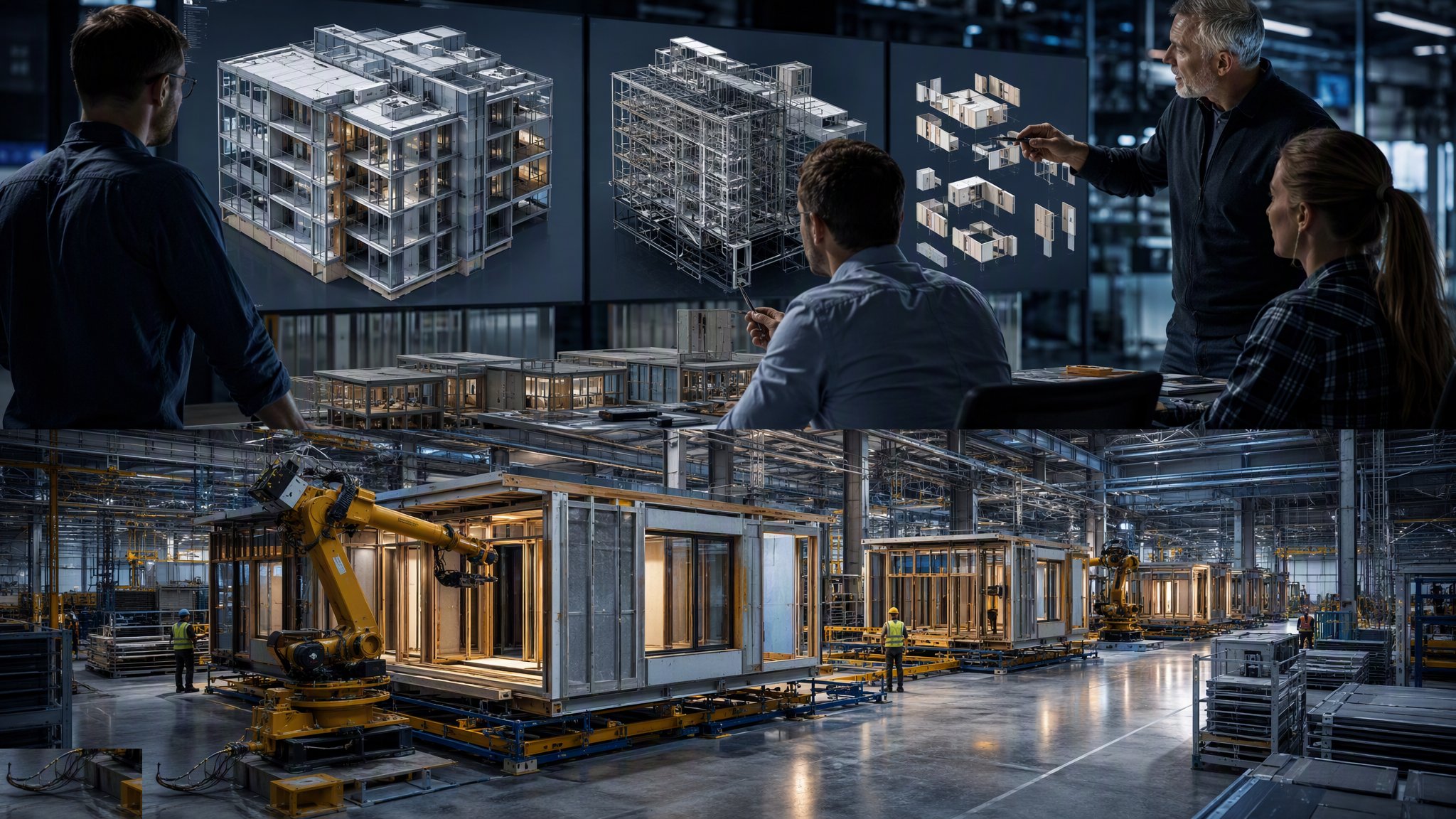
Component DfMA is the entry point. Rather than reconceiving the whole building around manufacture, the design team identifies individual elements that are better made in a factory than on a scaffold, and designs those elements to be manufactured, delivered and assembled. A unitised facade panel, a precast stair flight, a prefabricated bathroom wall, a factory-made roof cassette, a pre-assembled balcony, a structural steel section delivered with its connections and fire protection already applied - each is a component that arrives complete and is fixed into an otherwise conventional building. The rest of the project proceeds much as it always did.
The appeal is that it is reversible. The project keeps a conventional structure, a conventional procurement route and a conventional site organisation, and gains the benefits of factory production only where they are clearly worth having. If a component does not work out, it can be built the traditional way instead without unravelling the scheme. That makes component DfMA the right first move for a client with no off-site experience, for a one-off building, and for any project where the design has to stay flexible for commercial or planning reasons. It is also how most design teams learn the discipline, because the habits it demands - fixing dimensions early, designing the joint rather than the element, and thinking about how the thing is lifted - are the same habits the deeper approaches require.
The limitation is equally clear: the savings are proportionate to the commitment. Because the building is not designed as a manufactured product, the components sit within a site-built structure whose tolerances they must accommodate, and the interfaces between manufactured and site-built work remain the awkward part. The programme benefit is real but partial, since only some activities move off site. And the same design-freeze discipline still applies to each component - once a facade panel is in production, the opening it fits into is fixed. Projects that treat component DfMA as an ordinary procurement decision rather than a design decision usually find that out late, when a component arrives that is exactly right and the building is not.
How does Component DfMA work, step by step?
- 1
Step 1: Identify the candidate components
The team reviews the design for elements that repeat, that are difficult or slow to build in position, that are high risk to construct at height, or that demand quality hard to achieve on site. Facades, stairs, balconies, roof cassettes, bathroom walls, structural connections and services assemblies are the usual candidates. Each is assessed on its own merits rather than adopted as a package - the objective is to find the elements where manufacture genuinely pays, not to maximise the amount of off-site content.
- 2
Step 2: Test the business case for each candidate
For each component the team weighs the tooling and design cost, the transport and lifting implications, the programme saving, the quality benefit and the risk transferred. Some candidates fail the test - a component made twice rarely justifies the setup. The output is a short list the project commits to, and an explicit decision to build the rest conventionally. Being honest at this stage prevents the common failure of adopting off-site content for its own sake.
- 3
Step 3: Design the component and its interfaces together
The component is designed with its manufacturer, and its interfaces are designed with equal care. How it is fixed, how it is sealed, how services pass through it, how it is fire-stopped, how it accommodates movement and how it can be replaced in service are all resolved now. The interface is where component DfMA succeeds or fails, because it is the one part still made on site by hand against a factory-made element that will not adjust.
- 4
Step 4: Fix the tolerances explicitly
A manufactured component is made to a fine tolerance and a site-built structure is not. The design team decides where the difference is absorbed - in an adjustable bracket, a designed gap, a shimmed connection or a cover detail - and states it. The manufacturing tolerance, the setting-out tolerance of the receiving structure and the adjustment available in the connection are all set out by the designer and agreed by every party before manufacture. Leaving this to be worked out on site is the single most reliable way to generate a dispute.
- 5
Step 5: Freeze the component and start production
The component design is frozen and released for manufacture, and the project accepts that the surrounding design must now follow it. A first-off unit is inspected and signed off as the benchmark for the production run. The freeze point is written into the programme with a date attached, because a component freeze that is not diarised is a component freeze that slips.
- 6
Step 6: Manufacture, test and identify
Components are made to the benchmark and inspected before dispatch, with their tests and checks recorded against a unique identity. Any performance testing the specification requires - weather testing on facade units, load testing on structural components - is carried out on samples or on each unit as the design demands. Protection for transport is designed as part of the component rather than improvised at the loading bay.
- 7
Step 7: Survey the receiving structure before delivery
Before components are delivered, the structure they will fix to is surveyed as built. Deviation is measured against the tolerance that was agreed, and where it exceeds it, the structure is corrected or the connection is adjusted with the designer's agreement - before the component arrives, not with it hanging on a hook. This one step removes most of the site problems associated with manufactured components.
- 8
Step 8: Install, seal and record the interfaces
Components are delivered to a sequence matched to the structure and installed as a planned handling or lifting operation designed by the appointed person. Fixings are installed and inspected as designed, the interfaces are sealed, fire-stopped and made good, and every interface is inspected and recorded before it is concealed. The component itself is rarely the problem in service; the junction between it and the building usually is.
What are the benefits of Component DfMA?
- Low commitment - the project keeps a conventional structure, programme and procurement route
- Applied only where manufacture clearly pays, component by component
- Reversible if a component does not work out, without unravelling the scheme
- Moves the most difficult or highest-risk elements off scaffolds and into a factory
- Builds the design team's and the client's off-site experience with limited exposure
- Improves quality and consistency on the elements that matter most
What are the limitations of Component DfMA?
- The savings are proportionate to the commitment - partial adoption gives partial benefit
- Interfaces between manufactured and site-built work remain the main risk
- Each component still demands its own design freeze, which the wider design must then respect
- Site tolerances have to be tightened or absorbed by adjustable connections
- Low-volume components rarely justify their tooling and design cost
- Coordination effort is significant relative to the scale of the benefit
What is Component DfMA best suited for?
What plant does Component DfMA need?
- Manufacturer's factory facilities appropriate to the component being made
- First-off inspection and benchmarking facilities
- Purpose-designed transport frames and protection for each component type
- Survey equipment for as-built checks of the receiving structure
- Crane, hoist or handling equipment for the planned installation operation
- Adjustable brackets, shims and proprietary fixings as designed for the interface
How is Component DfMA quality-checked?
- Documented business case and decision for each component adopted
- Interface details designed, agreed and issued before manufacture
- Tolerance regime stated by the designer and agreed by manufacturer and installer
- First-off component inspected and signed off as the production benchmark
- Manufacturing and any performance test records held per component identity
- As-built survey of the receiving structure completed before delivery
- Fixings inspected against the design at installation
- Sealing, fire-stopping and interface make-good inspected and recorded before concealment
More design for manufacture and assembly methods
Next method
Platform approach (P-DfMA)