Cutter suction dredging (CSD)
A stationary dredger that cuts hard material at the face and pumps it straight ashore.
Last updated 2026-09-06
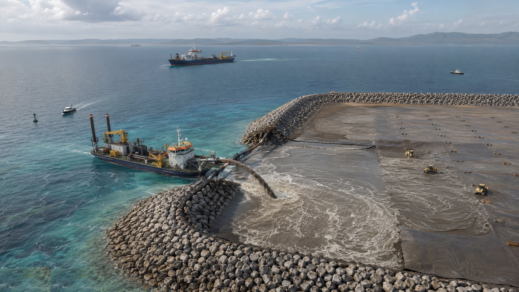
What is Cutter suction dredging (CSD)?
A cutter suction dredger works from a fixed position rather than on the move. A rotating cutter head on the end of a ladder is lowered to the face and grinds into the material, and a suction mouth immediately behind it draws the loosened mixture into the pump. The dredger holds station on spuds - large steel piles dropped through the hull into the seabed - and swings from side to side on anchored wires, cutting an arc across the face. When the swing is complete it steps forward on the spuds and cuts the next arc. The spoil does not go into a hopper. It is pumped continuously through a floating and shore pipeline, sometimes with booster pumps, straight to the reclamation area or the disposal site.
That continuous pumping is the type's great advantage. There is no cycle time, no sailing and no discharge operation - once the pipeline is connected and the face is being cut, production runs continuously. Combined with a powerful cutter head, that makes it the natural choice for capital dredging in stiff clay, compacted sand, weathered rock and even blasted rock, and for building a reclamation directly, since the material arrives at the fill area as a pumped slurry ready to be placed. Large cutter dredgers are among the most powerful pieces of plant in construction.
Its weaknesses come from being stationary. It sits on spuds and anchors in a spread of wires that other vessels must keep clear of, so it obstructs navigation and needs careful coordination with the port authority. It is exposed to weather and swell in a way a ship is not, so open-water working is limited and downtime can be significant. The pipeline is a project in itself - it has to be floated, laid, connected, moved as the works advance and protected where it crosses navigation - and a pipeline failure stops production instantly. Anchor handling is continuous work for attendant tugs. And where the material is rock, it may need blasting or a rock cutter head before the dredger can make progress at all.
How does Cutter suction dredging (CSD) work, step by step?
- 1
Step 1: Characterise the material and plan the attack
The investigation determines whether the material can be cut at all: strength, density, cementation and the presence of rock all decide the cutter head, the power required and the production that can realistically be expected. The designer and the marine contractor plan the cut - the sequence of swings and steps, the depth of each cut, and where the dredger will start and finish - along with the consents, the disposal or reuse route, and the environmental conditions the regulator has attached.
- 2
Step 2: Mobilise the dredger and lay the pipeline
The dredger is towed or sailed in and positioned, and the discharge pipeline is assembled: floating line across the water, submerged line where it crosses navigation, and shore line to the discharge point, with booster pumps where the distance or the lift demands them. The pipeline route is agreed with the port authority and marked, since it is a hazard to other vessels. Anchors and wires are laid out for the swing, and the spuds are prepared.
- 3
Step 3: Set the spuds and start cutting
The working spud is dropped to hold the stern, and the dredger swings the ladder across the face on its anchor wires while the cutter head rotates and grinds into the material. Cut depth per swing, swing speed and cutter rotation are controlled together to keep the mixture density high without choking the pump. The dredge master works to the plan and to the survey, not to the feel of the machine alone.
- 4
Step 4: Step forward and repeat
When the swing has cut the full arc, the dredger steps forward on its spuds - alternating between the working spud and the auxiliary - and cuts the next arc. Steps are typically a few metres and the process repeats, advancing the dredger along the cut. Positioning is by survey-grade equipment so that the cut arcs sit where the plan says, and the record of what has been cut is built up continuously.
- 5
Step 5: Pump continuously to the discharge point
The mixture is pumped without interruption to the reclamation or disposal area. Pipeline pressure, flow and density are monitored, because a fall in density means the cutter is not feeding the pump and a rise in pressure warns of a blockage. Booster pumps are manned and monitored. Where the discharge is into a reclamation, the placement of the slurry at the far end is managed as its own operation with its own bunds, weirs and return water arrangements.
- 6
Step 6: Deal with hard material
Where rock or very hard material is met, the options are a rock cutter head with heavy picks, pre-treatment by blasting, or a change of plant. Blasting underwater is a separate operation with its own consents, exclusion zones and environmental controls, particularly around marine mammals, and it is planned and permitted well in advance. The decision to blast is not one taken on the spot when production drops.
- 7
Step 7: Survey progress and control levels
Multibeam surveys track the cut face and the achieved levels, and the cut plan is updated from them. The dredger works to a design level with a tolerance, and both overdredging and leaving high spots are defects. Where the cut runs close to a quay wall or a structure, the stand-off and the sequence come from the designer, because removing support in front of a wall changes what that wall is carrying.
- 8
Step 8: Demobilise and close out
The pipeline is recovered, anchors and wires lifted, and the dredger demobilised. A final multibeam survey of the dredged area is issued as the acceptance record, with volumes reconciled against the production logs and against the volume delivered to the reclamation. The environmental monitoring record is closed out against the consent conditions and reported to the regulator.
What are the benefits of Cutter suction dredging (CSD)?
- Cuts hard material - stiff clay, compacted sand, weathered rock - that a trailer cannot touch
- Continuous production with no loading, sailing or discharging cycle
- Pumps spoil directly to a reclamation, delivering fill exactly where it is wanted
- Very high output over short to medium discharge distances
- Precise cutting to a designed level and profile because the dredger is held in position
- Booster pumps extend the discharge distance without adding barges or vessels
What are the limitations of Cutter suction dredging (CSD)?
- Stationary and anchored, so it obstructs navigation and needs constant coordination with the port authority
- Exposed to weather and swell, with significant downtime in open water
- The pipeline is a major operation and a single point of failure for the whole production chain
- Anchor and wire handling needs attendant tugs and is continuous work
- Rock may still need blasting or a rock cutter head, with separate consents and controls
- Mobilisation and demobilisation of a large cutter dredger are slow and expensive
What is Cutter suction dredging (CSD) best suited for?
What plant does Cutter suction dredging (CSD) need?
- Cutter suction dredger with interchangeable cutter heads including rock heads
- Spuds, spud carriage and anchor and wire spread with attendant tugs or anchor handlers
- Floating, submerged and shore discharge pipeline with booster pump stations
- Reclamation placement equipment - bulldozers, excavators and weir structures - at the discharge end
- Multibeam survey vessel and positioning equipment for the cut
- Turbidity monitoring and environmental observation equipment to the consent regime
How is Cutter suction dredging (CSD) quality-checked?
- Material characterisation confirmed against what is actually cut, with the cut plan updated
- Position, cut depth, swing and step recorded continuously through survey-grade positioning
- Pipeline pressure, flow and mixture density logged and used to control production
- Interim multibeam surveys used to control level, with overdredging treated as a defect
- Stand-off and sequence near existing structures followed as the designer specified
- Final acceptance survey issued with volumes reconciled against production and placed fill