Access trestles and conveyor galleries
The long approach - a repeating piled structure carrying road, services or a conveyor out to the berth.
Last updated 2026-09-06
What is Access trestles and conveyor galleries?
Where a berth stands off in deep water, something has to connect it to the shore. That something is a trestle: a long, repetitive piled structure carrying a roadway, pipelines, cables or a bulk conveyor out to the jetty head. Structurally it is the simplest marine work there is - a bent of piles, a headstock, a deck span, repeated as many times as the distance requires. Commercially it is often the largest single element of a marine terminal, because a trestle can run for hundreds of metres or more, and the difference between a good and a bad production rate is multiplied by every bent.
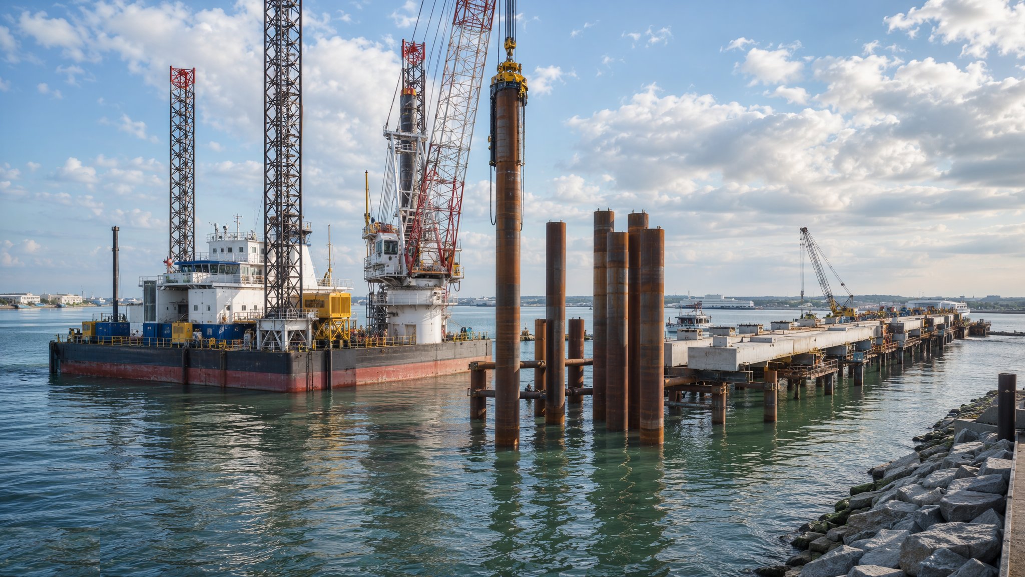
That repetition is the whole engineering argument. Trestles are designed to be built by a cycle rather than by a sequence, so the marine contractor typically sets up a spread that installs a bent, moves forward, and installs the next, sometimes using the completed structure itself as the access and delivery route. On most projects the deck is precast for exactly the reason it is precast on a jetty - to keep wet work over water to a minimum - and the units are delivered along the finished trestle from the shore rather than by barge, which removes the sea state from the delivery equation once the structure is far enough advanced.
A conveyor gallery adds a second layer of complexity because the structure now carries a machine. The conveyor has its own alignment tolerances, its own dynamic loads, its own drive and tensioning arrangements, and usually its own enclosure to control dust and spillage over the water. Transfer towers at each end and at any change of direction are heavy, concentrated structures that interrupt the repetition. On top of that come the services almost every trestle carries - firewater, power, control, communications and often product pipelines - each with its own supports, expansion arrangements and access requirements. The result is that the trestle deck is rarely just a deck, and coordination of what sits on it usually decides its width and its structural depth.
How does Access trestles and conveyor galleries work, step by step?
- 1
Step 1: Fix the alignment and the deck arrangement
The route is set by where the berth needs to be and by what the seabed, navigation and environmental constraints allow. The deck arrangement then follows from what it must carry: carriageway width, footway, pipe racks, cable routes and conveyor space, all coordinated before the structural depth is fixed. On most projects the trestle also has to accommodate maintenance access to everything it carries, which is a stronger driver of its width than the traffic. Getting this coordination done early is what keeps the structure repetitive.
- 2
Step 2: Design for the cycle, not for the single bent
A trestle is designed to be built by a repeating operation, so the designer and the marine contractor agree the bent spacing, the pile arrangement, the headstock form and the deck unit type against the plant that will build it. Standardising every element so that one bent is identical to the next is worth more than any structural refinement, because the saving is multiplied by the number of bents. Where the seabed profile changes along the route, the design usually absorbs it in pile length rather than in changed geometry.
- 3
Step 3: Establish the marine spread and the first bents
The first few bents are installed from floating or jacked-up plant working from the shore end, and they are treated as a proving exercise: the template, the pitching method, the driving plant, the survey routine and the crew's cycle are all shaken down before production rates are expected. Problems found in the first bents are cheap; the same problems found at bent forty are multiplied by the ones already built. The learning is written into the method statement before the campaign proper begins.
- 4
Step 4: Drive the bents to the cycle
Each bent is set out, the template positioned, the piles pitched and driven to the designer's founding criteria, and the heads cut to level. The survey record for each bent is taken before the plant moves forward, because the deck units for that bent depend on it. Where the plant works off the completed structure, a leapfrogging arrangement is used in which the crane stands on the last completed bent and builds the next - a temporary works case that is designed for the crane loads on a partly complete structure rather than on the finished one.
- 5
Step 5: Land the headstocks and the deck units
Headstocks are landed as precast units or cast in situ on hanging formwork, and the deck beams and planks follow. Once a few bents are complete the deck itself becomes the delivery route, and units are brought out by road transport from the shore, which is faster, cheaper and far less weather-dependent than barging them. In situ stitches tie the units together. On most projects this changeover from marine delivery to land delivery is a planned milestone, because it changes the whole economics of the remaining structure.
- 6
Step 6: Install the services and the pipe supports
Pipe racks, cable trays, firewater mains, power and control cabling, lighting and drainage are installed along the completed deck. Marine trestles are long, exposed and thermally active, so expansion arrangements, sliding supports, anchor points and flexible connections are all detailed and installed to the designer's arrangement rather than adjusted on site. Corrosion protection of supports and fixings is completed as the work proceeds, because access from a finished trestle is much harder than access during construction.
- 7
Step 7: Erect the conveyor gallery and transfer towers
Where the trestle carries a bulk conveyor, the gallery steelwork is erected in shop-fabricated sections lifted into place along the deck, and the transfer towers at the ends and at any change of direction are erected as heavy standalone structures. The conveyor idlers, belt, drives, tensioning arrangement and dust control equipment are installed to the supplier's alignment tolerances, which are much tighter than the structural ones. Belt alignment is the single most common source of trouble on a conveyor and it is set, checked and recorded rather than trusted.
- 8
Step 8: Commission, protect and hand over
Services are pressure-tested and energised, the conveyor is run empty and then loaded through a commissioning programme, and lighting, safety systems, walkways, handrails and escape routes are completed. Cathodic protection is bonded and commissioned along the whole structure. The handover record covers the as-built survey of every bent, the driving records, the precast unit references, the service test records and the conveyor commissioning, together with an inspection and maintenance regime for a structure the operator will be walking for decades.
What are the benefits of Access trestles and conveyor galleries?
- Highly repetitive - once the cycle is established, production rates are predictable and fast
- Reaches a deep-water berth without dredging an approach or building a solid causeway
- Leaves the water largely open, so flow, siltation and navigation are much less affected than by a causeway
- The completed structure becomes its own access and delivery route, removing sea state from later deliveries
- Carries road, services and conveyors in one coordinated structure rather than several
- Standardised bents allow precasting and fabrication to run well ahead of installation
What are the limitations of Access trestles and conveyor galleries?
- Long structures multiply every error, so a poor early decision is repeated many times over
- Coordination of services, pipe racks and conveyors usually drives the deck width and depth
- Exposed for its whole length, with a large corrosion protection and inspection liability
- Thermal movement over a long structure needs careful expansion detailing at every service run
- Conveyor galleries add machine tolerances, dust control and a mechanical commissioning tail
- Access for maintenance is inherently awkward and has to be designed in from the start
What is Access trestles and conveyor galleries best suited for?
What plant does Access trestles and conveyor galleries need?
- Jack-up or barge-mounted piling spread for the early bents, with anchor handling support
- Deck-mounted crane working off the completed structure for the leapfrogging cycle
- Vibratory and impact hammers with piling templates for each bent
- Road transport and lifting equipment for delivery of precast units along the finished deck
- Steel erection and alignment equipment for gallery sections and transfer towers
- Survey equipment for bent-by-bent as-built records and conveyor alignment
How is Access trestles and conveyor galleries quality-checked?
- As-built survey of each bent recorded before the plant moves forward
- Driving records for every pile checked against the designer's founding criteria
- Temporary works design and check for crane loads on the partly complete structure
- Precast unit references, bearing inspection and stitch pour records for each bent
- Service pressure tests, expansion support installation checks and corrosion protection records
- Conveyor alignment, belt tracking and commissioning records handed over with the structure