Axle counter detection
Counting axles in and out of a section, instead of using the rails to detect the train.
Last updated 2026-09-05
What is Axle counter detection?
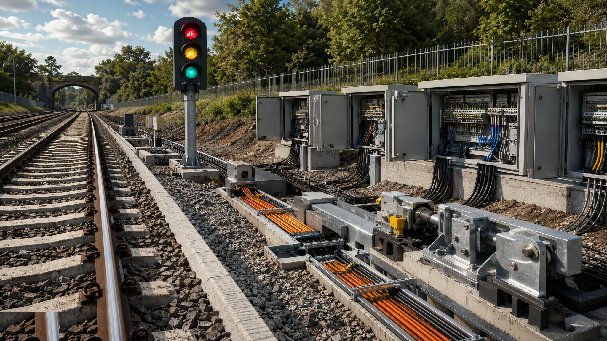
An axle counter detects trains by counting. Equipment at each end of a section counts the axles that pass into it and the axles that pass out, and when the two counts match the section is clear. The rails play no part in the detection, which is the whole point. A track circuit depends on the electrical condition of the rails, the joints and the ballast beneath them, and on routes where that condition is difficult to maintain the detection becomes unreliable. Axle counters sidestep the problem entirely by moving the detection to equipment mounted at the trackside at defined points, leaving the track free to be simply track.
That difference changes the shape of the installation. Instead of equipment distributed along the whole length of every section, there are counting heads at the section boundaries and an evaluator that does the arithmetic. Section lengths are not constrained by the electrical limits that apply to track circuits, so the designer has more freedom in where to put boundaries, and long sections through tunnels, over bridges and across areas of difficult track become practical. There is less to be affected by ballast condition, water and railhead contamination, and on an electrified route the detection is not entangled with the traction return arrangement in the way a track circuit is. Maintenance effort shifts from a long lineside asset to a smaller number of discrete pieces of equipment.
The trade-off is a different kind of discipline. Because the system works by counting, it needs to know that the section is genuinely clear before it starts counting again, and any event that disturbs the count - a vehicle removed from the section, a movement that does not complete, equipment interrupted - has to be resolved by a controlled restoration carried out by authorised staff before the section can be used normally again. That is an operational routine as much as a technical one, and it needs to be understood and resourced by the infrastructure manager from the day the system enters service. The other consequence of moving detection off the rails is that a broken rail within a section is not registered by the detection system as it would be by a track circuit, so the infrastructure manager addresses that through inspection and other means. All design, testing and entry into service follow an independently checked assurance process, and no detail of that process, of the restoration procedure or of the system's behaviour appears here.
How does Axle counter detection work, step by step?
- 1
Step 1: Establish why the detection is being changed
Axle counters are usually chosen for a reason: track circuits performing poorly because of ballast condition, drainage, contamination or the electrical environment, or a layout where section lengths are awkward to achieve with track circuits. The infrastructure manager and the signalling engineer establish the case, because the change carries operational consequences as well as technical benefits, and those consequences have to be accepted before the design proceeds.
- 2
Step 2: Design the section boundaries and the equipment layout
The signalling engineer sets out where counting heads go, how sections are divided and where evaluators and their power and communication links sit. Freedom from the electrical constraints that limit track circuits means the boundaries can follow the operating need more closely. Cable and communication routes between heads and evaluators are designed at the same time. The design is independently checked within the infrastructure manager's assurance process before anything is installed.
- 3
Step 3: Survey the trackside and confirm the mounting positions
Counting heads are mounted at defined positions on the track, so each position is surveyed and confirmed: track condition, room for other equipment, access for maintenance and the route for the cabling. Positions that are difficult to reach make future maintenance harder, and on a system whose whole advantage is reduced maintenance effort that is worth resolving at design stage rather than after handover.
- 4
Step 4: Install cable routes, evaluators and power supplies
Cable route, equipment housings, evaluators and power supplies are installed along the route. There is generally less of this than a comparable track circuit installation requires, but it is the same kind of work in the same live railway corridor, with the same access, protection and buried services constraints. Communication links between the trackside equipment and the interlocking are part of this stream and are designed alongside it.
- 5
Step 5: Fit the counting heads at the section boundaries
Counting heads are fitted to the rail at the designed positions and connected back to their evaluators. The physical fitting is small-scale, precise work in a possession, and the positions have to be recorded accurately because track work carried out later needs to know they are there. Coordination with the track engineer matters: a rail replaced without regard to the equipment on it creates a signalling problem out of a track project.
- 6
Step 6: Establish the restoration arrangements
Because the system counts, there has to be a defined, controlled way of restoring a section to normal working after any event that disturbs the count, carried out by authorised staff. The infrastructure manager defines that arrangement, trains the staff who will use it and resources it before the system enters service. This page states that the requirement exists and gives no procedure, no detail and no criteria, because it is a matter for qualified and authorised staff working to the infrastructure manager's rules.
- 7
Step 7: Test and bring into use under the assurance process
Testing and entry into service are carried out by competent, qualified signalling staff within the infrastructure manager's independently checked assurance process. As with any signalling change, this stage needs the railway closed, needs the system complete and dominates the programme. No detail of the testing or the acceptance arrangements is given here.
- 8
Step 8: Hand over with the maintenance and inspection regime
Handover includes the as-installed records, the position of every counting head, the maintenance regime for the equipment and the infrastructure manager's arrangements for the matters the detection system does not itself cover, including rail inspection. The regime is agreed as part of the project. The maintenance saving axle counters offer is only realised where the smaller asset base is actually maintained on a defined cycle.
What are the benefits of Axle counter detection?
- Detection does not depend on the electrical condition of the rails, joints or ballast
- Performs where track circuits struggle - poor drainage, contamination and difficult track conditions
- Section lengths are not constrained by the electrical limits that apply to track circuits
- Fewer distributed lineside assets, so less to inspect and maintain along the route
- Long sections through tunnels and over structures become practical
- Detection is not entangled with the traction return arrangement on an electrified route
What are the limitations of Axle counter detection?
- Needs a defined, controlled restoration carried out by authorised staff after any event that disturbs the count
- That restoration is an operational routine that has to be trained and resourced from day one
- A broken rail within a section is not registered by the detection system, so the infrastructure manager covers it by other means
- Counting heads are fitted to the rail, so track work has to be coordinated around them
- Equipment positions that are hard to reach undermine the maintenance advantage
- Testing and entry into service are as demanding as for any signalling change
What is Axle counter detection best suited for?
What plant does Axle counter detection need?
- Road-rail plant for cable route installation and material delivery
- Excavation and foundation plant for equipment housings and power supplies
- Cable pulling, handling and termination equipment
- Precision fitting equipment for mounting counting heads to the rail
- Survey equipment for confirming and recording equipment positions
- Test equipment used by qualified signalling testers within the assurance process
How is Axle counter detection quality-checked?
- Case for changing the detection method agreed with the infrastructure manager before design
- Scheme design independently checked as part of the infrastructure manager's assurance process
- Every counting head position surveyed, confirmed and accurately recorded for future track work
- Cable, communication and power installations recorded as installed
- Restoration arrangements defined by the infrastructure manager, with authorised staff trained and resourced before entry into service
- Testing and entry into service carried out only by competent, qualified signalling staff under the independently checked assurance process
- Maintenance and inspection regime, including the infrastructure manager's rail inspection arrangements, agreed and handed over