Signalling & Telecoms
Signals, point machines, train detection, interlockings and the telecoms backbone - the systems that keep trains apart and tell them where to go.
Last updated 2026-09-05
Typical duration
Lineside installation runs 6–18 months on a major scheme; staged interlocking testing and commissioning typically adds several months per control area, and driverless metros measure the full test programme in years.
What is Signalling & Telecoms?
Signalling is the railway's nervous system. Its job is brutally simple - keep trains a safe distance apart and set their routes - but the machinery that does it spans colour-light signals at the lineside, point machines that throw and lock the switches, track circuits and axle counters that prove where the trains are, and the interlocking at the centre that refuses to set a route that conflicts with another. Modern interlockings are solid-state computers in equipment buildings, but the principle is Victorian: nothing moves until it is proven safe, and every failure must fail to danger. Around the signalling runs the telecoms backbone - fibre along the route, location cases and equipment buildings, GSM-R radio for driver-to-signaller voice and, increasingly, the data bearer for in-cab signalling.
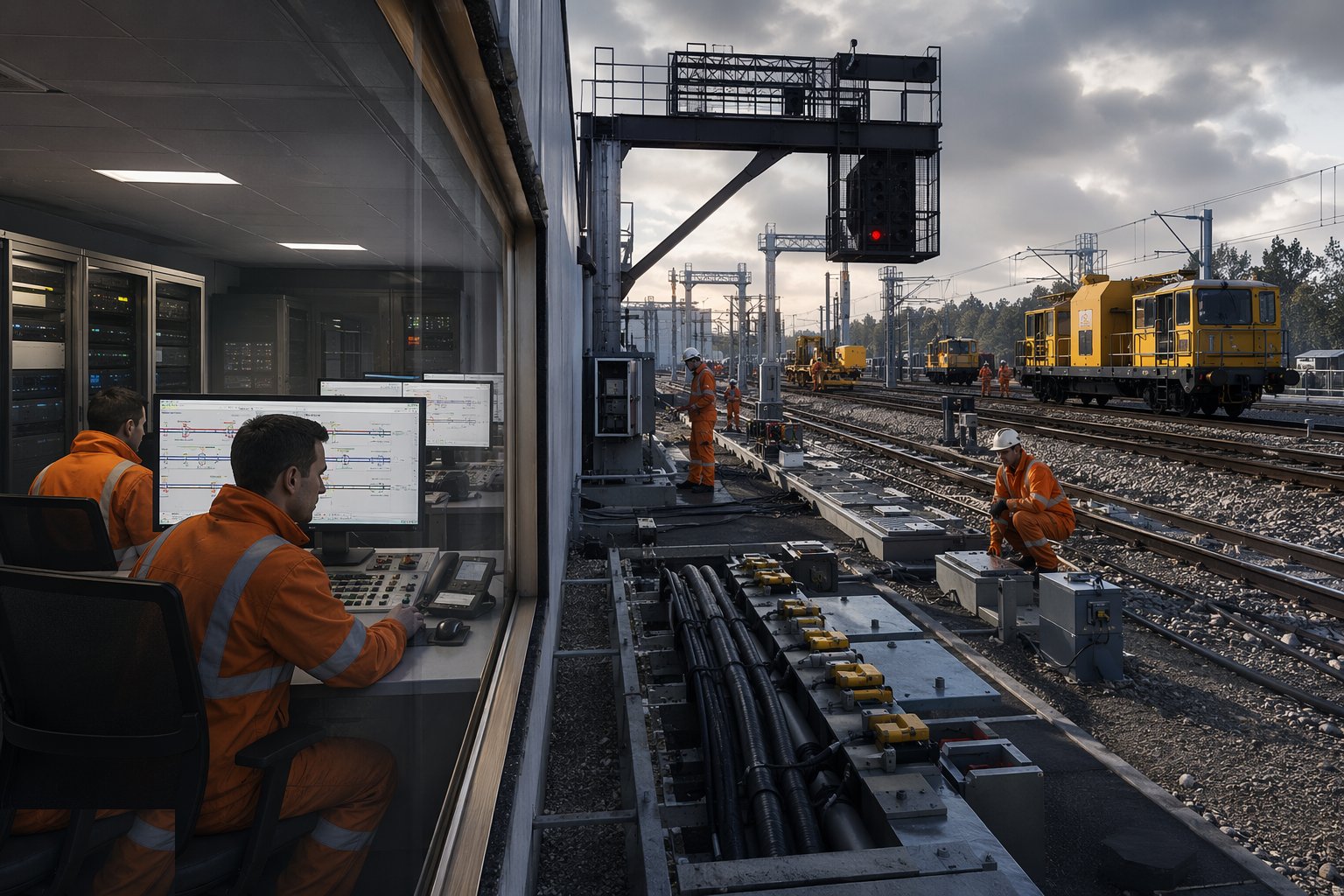
The construction sequence starts in the ground: cable routes and troughing along the corridor, ducts under the track, then the location cases - the lineside equipment housings - and the cables themselves, pulled, jointed and terminated to schedules that run to thousands of cores. Signals are erected and aligned, point machines fitted and detected, track circuits tuned or axle counter heads set, and every circuit is then proved end to end in the testing rooms: wire counts, function tests, and finally the principles testing and independent checking that let an interlocking be commissioned. ETCS - the European Train Control System - moves much of this into the cab: trackside beacons or radio-based movement authority, an interlocking talking to a radio block centre, and far less lineside hardware to maintain, at the cost of a far more demanding software and integration regime.
In the Gulf, new-build metros arrive fully modern: Dubai, Doha and Riyadh run driverless or high-automation operation with communications-based train control - CBTC - where the signalling is a radio system with an interlocking behind it and platform screen doors as part of the train separation story. The construction consequence is that the telecoms backbone is no longer supporting cast; it carries the train control itself, so fibre diversity, radio coverage surveys in tunnels and EMC discipline in equipment rooms are front-page testing items. GSM-R remains the main-line voice standard where conventional operation applies, and every route still needs its location cases, its earthing and bonding, and its maintenance access designed in rather than discovered later.
Compare the methods at a glance

When and why is Signalling & Telecoms used?
Signalling and telecoms installation follows the track and runs in parallel with electrification, and its commissioning is the single longest integration exercise on the project - every cable, every function and every failure mode has to be proven before a passenger train runs under signals. It matters because signalling is the licensed safety system: the railway does not legally operate without a proven interlocking, and the testing evidence - wire counts, function tests, principles test records - is the safety case. Get the installation records wrong and the testers inherit a puzzle instead of a system; rush the commissioning and the fault will be found by an operator in service, in front of passengers, at the worst possible time.
Walkthrough storyboard
The process in pictures, step by step - Step 1 of 6 - slide through the snapshots.
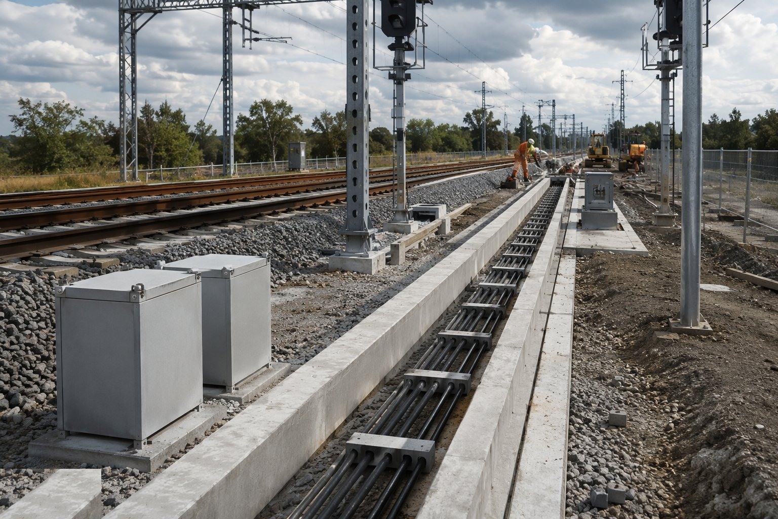
STEP 1
Build the cable routes and troughing
Install the lineside cable routes - concrete or polymer troughing, buried ducts, under-track crossings - on the corridor ahead of any equipment.
Types of Signalling & Telecoms
Explore each method in depth - benefits, limitations, plant and quality control on its own page.
Colour-light signalling with track circuits
The conventional main-line arrangement: multi-aspect colour-light signals - red, single yellow, double yellow, green in four-aspect territory - with train detection by track circuits, jointless audio-frequency types such as TI21 on electrified lines. Proven, maintainable and understood by every signalling tester on the network.
Explore this methodAxle counter detection
Train detection by counting axles in and out of a section with trackside heads, immune to the leaf-fall and rail-contamination problems that plague track circuits. Standard on new installations, and the heads, evaluators and reset logic all need proving as thoroughly as the circuits they replace.
Explore this methodETCS and in-cab signalling
Movement authority displayed in the cab: Level 1 with trackside beacons over existing signals, Level 2 with continuous radio from a radio block centre and no lineside signals at all. The construction content shifts from signals to radio coverage, data configuration and software testing - and the integration burden moves with it.
Explore this methodCBTC metro signalling
Communications-based train control for metros: continuous radio between train and trackside, moving-block headways and driverless operation where specified, integrated with platform screen doors. The highest automation and the highest software assurance burden - the dynamic test programme is measured in months, not weeks.
Explore this methodBest suited for
- Proving safe train separation on conventional, ETCS and CBTC railways
- The longest-lead commissioning activity on any railway project
- Metro automation where signalling, radio and platform doors are one integrated system
- Any route where the safety case lives or dies on test evidence
Signalling & Telecoms: step by step
- 1
Step 1: Build the cable routes and troughing
Install the lineside cable routes - concrete or polymer troughing, buried ducts, under-track crossings - on the corridor ahead of any equipment. Routes are surveyed, records kept of every duct and crossing, and the routes are proven clear by mandrel or test pull before cable is ordered. A blocked duct discovered at cable-pulling stage costs a possession and a night shift; the route survey is cheap insurance taken early.
- 2
Step 2: Install location cases and equipment buildings
Set the location cases and relocatable equipment buildings on their bases, connect their earthing and bond them into the route's earth electrode system, and terminate the incoming cables to the schedules. Every case is labelled, every core identified, and the terminations are torqued and checked - because the wire count that follows is only as good as the workmanship it counts, and a crossed pair found at commissioning can cost a week.
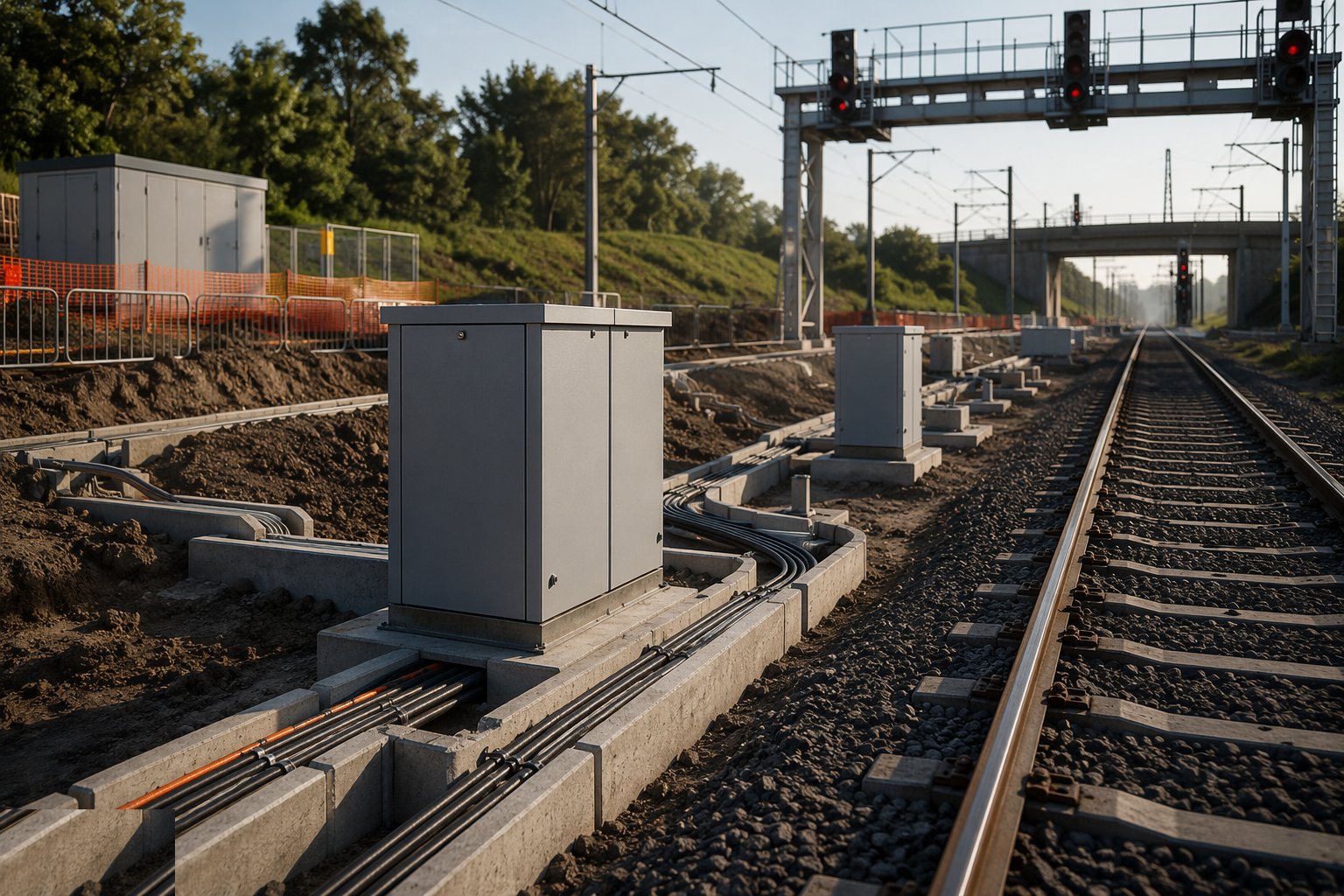
- 3
Step 3: Erect signals and fit point machines
Stand the signal structures, align the heads for the sighting committee - a signal is only legal if the driver can read it at braking distance - and fit the point machines with their detection, so the interlocking knows not just that the points moved but that they are locked and correctly lying. Machine torque, detection contacts and backdrive are all set and recorded per end, and every signal aspect is proved to show the right colour for the right route before anyone calls it installed.
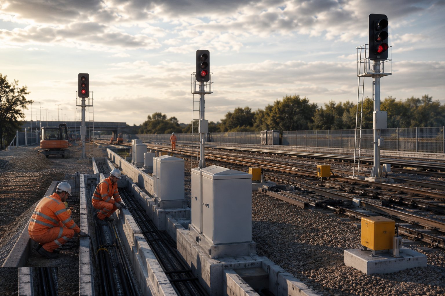
- 4
Step 4: Install train detection and the telecoms backbone
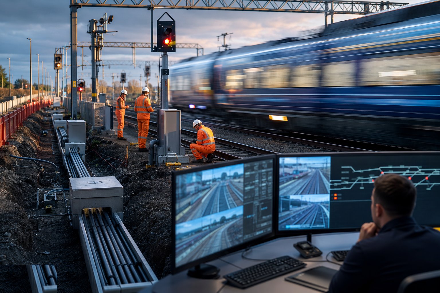
Tune the track circuits - shunt values, receiver levels, relay or electronic trackside equipment - or set the axle counter heads at their precise rail positions and prove the counting. In parallel, pull and splice the fibre backbone, build the transmission network, and survey the radio coverage: GSM-R along main lines, the CBTC radio network in metro tunnels with its leaky-feeder or antenna runs. Radio coverage is measured, not assumed - a dead spot in a tunnel is a failed test, not a shrug.
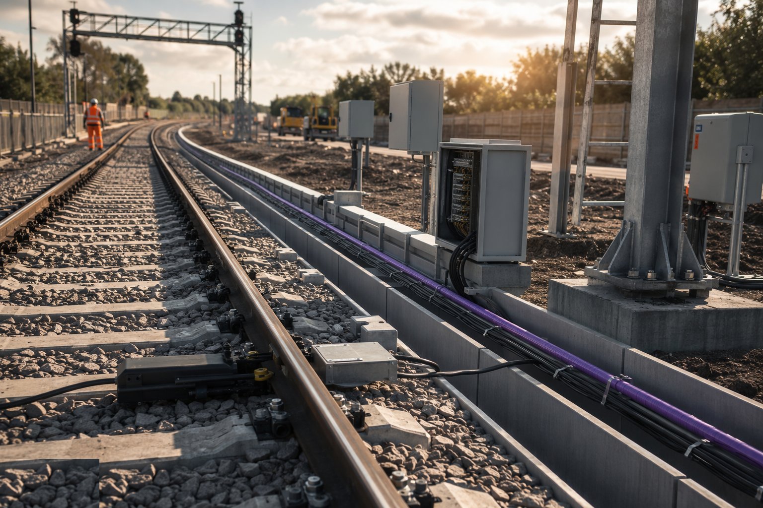
- 5
Step 5: Prove the interlocking in staged testing
Move into the test rooms and work the sequence: wire counts and insulation tests, then function testing of every route, aspect and detection circuit against the control tables, then principles testing - the independent proof that the interlocking logic itself implements the signalling principles - and finally the independent checking by a tester who was not involved in the build. Every test is signed, every anomaly closed out; the interlocking is commissioned only when the evidence stack says so, and the evidence stack is the product.
- 6
Step 6: Integrate, dynamically test and commission
Bring the systems together: interlocking to the SCADA and control centre, signalling to the platform screen doors, ETCS or CBTC to the trains, and the whole into the dynamic test programme with real rolling stock. Signal sighting is re-proven from the driver's seat at speed, interference between traction power and detection is hunted down and fixed, and the commissioned system is handed to the operator with its configuration records, test certificates and the maintenance regime it will live under for the next thirty years.
Plant & equipment
- Cable pulling and jointing equipment, duct rodders and mandrels
- Road-rail MEWPs and cranes for signal structures and equipment buildings
- Track circuit tuning and test sets; axle counter installation gauges
- Fibre splicing and OTDR test equipment
- Radio survey and coverage measurement equipment for GSM-R and CBTC
- Interlocking test rooms with simulation and data-logging rigs
- Insulation resistance and earth testing instruments
- Test trains and onboard recording equipment for dynamic proving
Quality control & testing
- Cable schedules and termination records completed and wire-counted per case
- Every signal sighted and approved by the sighting committee before commissioning
- Point machine torque, detection and backdrive recorded per end
- Function tests and principles testing signed off, with independent checking
- Fibre OTDR traces and radio coverage surveys filed as acceptance evidence
- Configuration control on all software and data - every version logged and approved
Safety watchpoints
- Working on or near the line under a planned safe system: possessions, lookouts, exclusion zones
- Electrical safety in location cases - supplies treated as live until proven isolated
- Confined space and tunnel working rules for metro radio and cable installation
- Manual handling of concrete troughing and location cases across kilometres of corridor
- Competency regime: only licensed signalling testers connect, alter or commission safety circuits
- Strict change control once the system is live for testing - no informal modifications, ever
Common defects to hunt
- Cables pulled before routes were proven - joints in troughing that should never have existed
- Terminations made without torque or labelling discipline - wire counts that take three attempts
- Signals erected before sighting - re-aligned at night in a possession, at test-train prices
- Radio coverage assumed from the drawings - dead spots found by the first dynamic test run
- Configuration records lagging the software - testers proving a version the trains are not running
- Independent checking squeezed by programme pressure - the one corner nobody can afford to cut
How long does Signalling & Telecoms take?
Typical duration: Lineside installation runs 6–18 months on a major scheme; staged interlocking testing and commissioning typically adds several months per control area, and driverless metros measure the full test programme in years..
Related processes
- Rail Formation & Trackbed
- Track Construction
- Rail Electrification - OLE & Conductor Rail
- Station Construction
- Systems Integration, Testing & Trial Running
- Colour-light signalling with track circuits - method
- Axle counter detection - method
- ETCS and in-cab signalling - method
- CBTC metro signalling - method
- Rail & Metro sector guide
- Transport Infrastructure - group of sectors