Colour-light signalling with track circuits
Signals at the lineside, and trains detected through the running rails themselves.
Last updated 2026-09-05
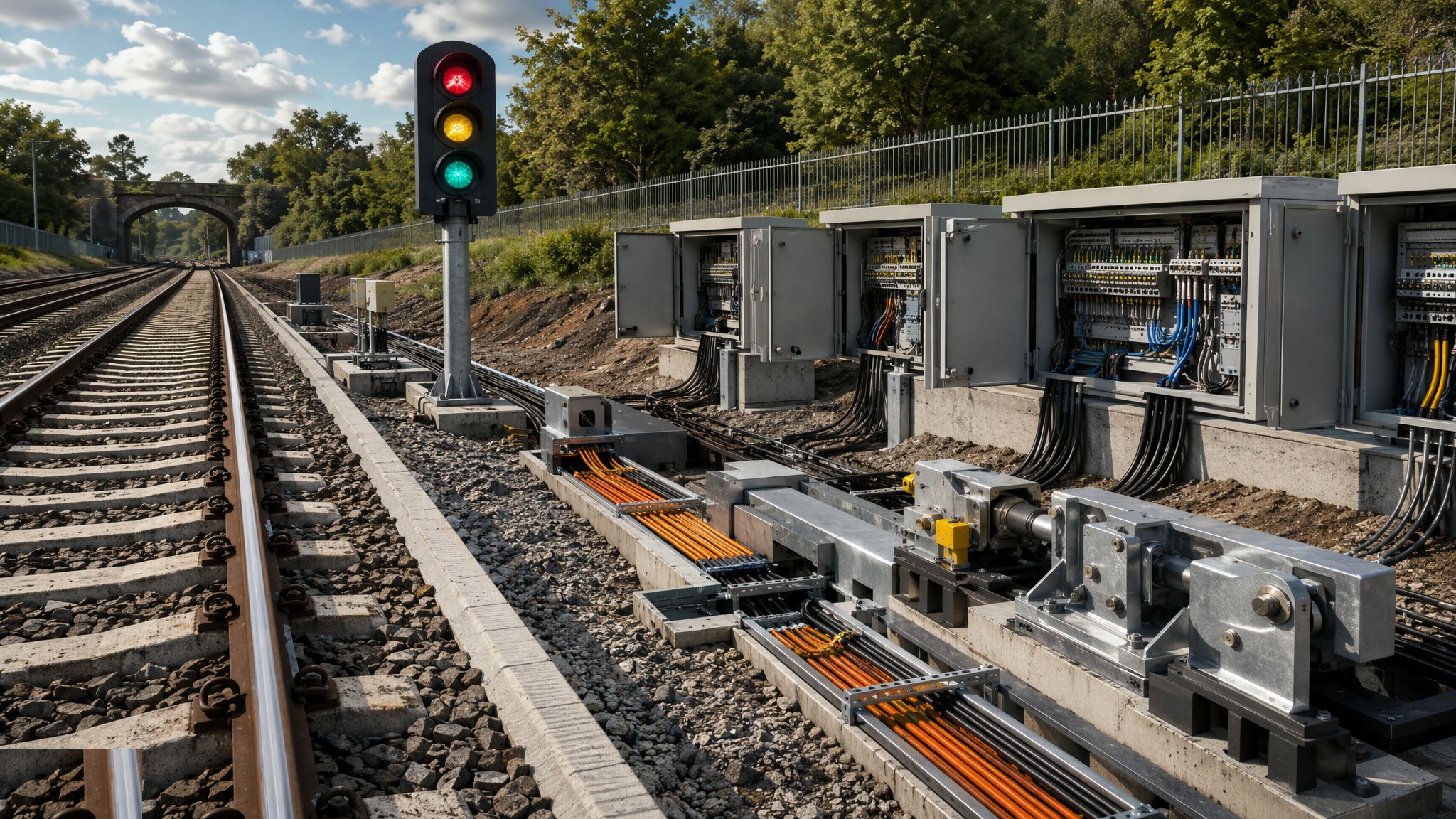
What is Colour-light signalling with track circuits?
Colour-light signalling is the arrangement most people picture when they think of railway signalling. Signals stand at the lineside and display an aspect to the driver, who reads it from the cab as the train approaches. Behind that simple picture sits a train detection system, because a signal can only show a safe aspect if the equipment knows where trains are. The long-established method of detecting them is the track circuit, which uses the running rails themselves as part of an electrical circuit. When a train occupies the section, its axles connect the two rails and change the circuit, and the signalling equipment registers the section as occupied. It is an elegant idea and it has been the backbone of railway signalling for a very long time.
What makes this a large construction undertaking is not the signals but everything that connects them. A conventional colour-light installation needs a great deal of lineside equipment: signal structures and their foundations, location cases along the route, equipment rooms, and cable routes running the length of the railway carrying power and signalling circuits between all of it. On a resignalling project the cabling is often the biggest single element of the physical works, and cable route condition is a recurring problem on older routes where troughing has been damaged, buried or filled with water over decades. The track itself becomes signalling equipment too, because a track circuit depends on the electrical condition of the rails, the joints and the ballast beneath them.
That dependence is also the system's weakness. Track circuits are sensitive to the condition of the track and to what is around it. Contamination on the railhead, poor ballast condition, water and, on an electrified route, the traction return current all affect them, and keeping them reliable is a continuous maintenance duty rather than a one-off commissioning task. The volume of lineside equipment adds to that burden: more cable, more location cases and more assets to inspect. Newer schemes therefore often move detection to axle counters or move the whole arrangement to in-cab signalling, while colour-light installations remain widespread and are renewed where wholesale change is not justified. Every aspect of signalling design, testing and entry into service follows an independently checked assurance process managed by the infrastructure manager, and no part of that process, and no interlocking or failure behaviour, is described on this page.
How does Colour-light signalling with track circuits work, step by step?
- 1
Step 1: Establish the operating requirement
Signalling exists to deliver a service, so the project starts with what the railway has to do: the trains to be run, the pattern of services, the junctions and crossovers required and the performance expected. The infrastructure manager and the operator agree that requirement, and the signalling engineer designs to it. Changing the operating requirement after design is well advanced is expensive, because so much of the physical installation follows directly from it.
- 2
Step 2: Survey the route and the existing equipment
A resignalling project inherits decades of accumulated equipment, cable and records of varying accuracy. The survey establishes what is actually there: existing signals and structures, cable routes and their condition, equipment rooms, power supplies and track condition. Cable route condition in particular is a common source of surprise, because troughing gets damaged, buried and flooded over the years and the records rarely say so. Finding this out early is what keeps the installation programme honest.
- 3
Step 3: Design the scheme and have it independently checked
The signalling engineer produces the scheme design covering signal positions, detection sections, control arrangements and equipment layout. That design is independently checked as part of the infrastructure manager's assurance process before anything is built. The technical content of the design, the interlocking arrangements and the behaviour of the system are matters for qualified signalling engineers working within that process, and none of it is set out here.
- 4
Step 4: Install the cable routes and lineside civils
Cable route is the bulk of the physical work. Troughing is laid or renewed along the route, cable is pulled in and terminated, and signal foundations, location case bases and equipment room buildings are constructed. This work takes place in a live railway corridor, so it needs access, protection and careful management around buried services and the earthworks either side of the track. On most projects the cabling determines the installation programme.
- 5
Step 5: Erect signals and install lineside equipment
Signal structures are erected on their completed foundations and location cases, equipment rooms and power supplies are installed and connected. Each item is straightforward on its own. The scale is what makes it a project: a route resignalling involves a very large number of small installations spread along many kilometres of railway, each needing access, each needing a record and each needing to be correct.
- 6
Step 6: Prepare the track for detection
Because the running rails form part of the detection circuit, the track has to be in the electrical condition the design assumes. That commonly means attention to rail joints, ballast condition and drainage ahead of commissioning, and coordination with the track engineer on any renewal happening at the same time. On an electrified route the interaction with the traction return arrangement is a design matter for the signalling engineer and is not described here.
- 7
Step 7: Test and bring into use under the assurance process
Signalling is tested and brought into use through a formal, independently checked assurance process run by the infrastructure manager and carried out by competent, qualified signalling testers. It is the most tightly controlled activity on the project and it dominates the programme, because it needs the railway closed, needs the whole system complete and cannot be shortened. No detail of the testing, the checks or the entry into service arrangements appears on this page.
- 8
Step 8: Hand over the asset and its maintenance regime
Handover includes the design records, the as-installed cable and equipment records, the spares and the maintenance regime the infrastructure manager will operate. A colour-light installation with track circuit detection carries a substantial ongoing inspection and maintenance burden, and the regime is agreed as part of the project rather than left to be worked out afterwards.
What are the benefits of Colour-light signalling with track circuits?
- The long-established arrangement, understood by drivers, signallers and maintainers alike
- Aspects are visible at the lineside, so no equipment is required on board beyond what the driver can see
- Works with any train that can be driven on the route, regardless of fitted equipment
- Detection through the rails also registers a broken rail condition within the detected section
- Mature supply chain, with well-established components, spares and competences
- Can be renewed in stages on a route where wholesale change is not justified
What are the limitations of Colour-light signalling with track circuits?
- A very large volume of lineside equipment and cable, which dominates the cost and the installation programme
- Track circuit performance depends on the condition of the rails, joints, ballast and drainage
- Continuous maintenance and inspection burden across many kilometres of lineside assets
- Cable route condition on older routes is frequently worse than the records suggest
- Capacity is limited by the fixed detection sections and the fixed positions of the signals
- Testing and entry into service need the railway closed and cannot be compressed
What is Colour-light signalling with track circuits best suited for?
What plant does Colour-light signalling with track circuits need?
- Road-rail plant for cable route installation, troughing and material delivery
- Excavation and foundation plant for signal bases and location case bases
- Cable pulling, handling and termination equipment
- Craneage for erecting signal structures and placing equipment rooms
- Track and drainage plant where the track has to be prepared ahead of commissioning
- Test equipment used by qualified signalling testers within the assurance process
How is Colour-light signalling with track circuits quality-checked?
- Operating requirement agreed with the infrastructure manager and the operator before design
- Route and existing asset survey completed, including cable route condition
- Scheme design independently checked as part of the infrastructure manager's assurance process
- As-installed records kept for every signal, location case, equipment room and cable run
- Track, joint, ballast and drainage condition confirmed ahead of commissioning
- Testing and entry into service carried out only by competent, qualified signalling staff under the independently checked assurance process
- Design records, as-built information, spares and the maintenance regime handed over with the asset
More signalling & telecoms methods
Next method
Axle counter detection