Multi-span and propped portal frames
Internal columns buy a much wider building - and the argument is always about where they land in the racking.
Last updated 2026-09-06
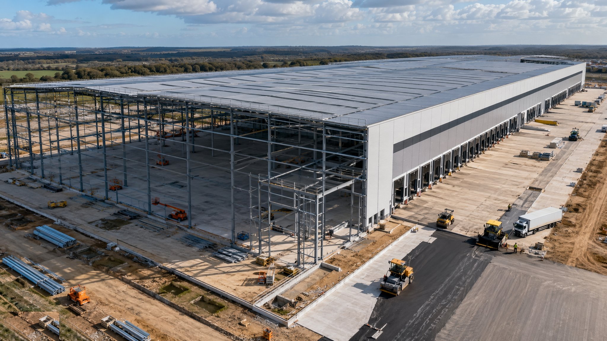
What is Multi-span and propped portal frames?
A multi-span portal frame is several portal frames placed side by side sharing internal columns, so a building that would be uneconomic as one clear span becomes straightforward as three or four. A propped portal is the same idea taken further, with a single internal prop supporting the rafter mid-span to cut the rafter depth. Both approaches exist for one reason: steel weight. Beyond a certain span the rafter gets so deep, and the frame so heavy, that adding a line of columns and halving the span costs far less than the extra tonnage. On very deep footprints - and modern regional distribution centres can be well over 150 m front to back - multi-span is often the only sensible structural answer.
The price is obstruction. Every internal column line is a permanent feature of the floor plan that the racking has to be arranged around, and columns in the wrong place waste far more floor area than their footprint suggests. A column standing in an aisle blocks a truck run. A column standing in a rack run costs a bay or forces a shortened run. On most projects the internal grid is therefore set to a multiple of the racking bay dimension so that columns fall inside a rack line rather than in a working aisle, which means the racking layout has to be known - or at least a credible assumption fixed - before the steel is designed. That is a commercial conversation as much as an engineering one, because a speculative building has no occupier to ask.
The other consequence is drainage and roof geometry. Multi-span roofs have valleys between the spans, and a valley gutter running the depth of a large shed is a serious piece of engineering and a serious maintenance liability. Valleys collect water, they collect debris, they need overflow provision, and a blocked valley gutter on a wide building is one of the more damaging failures a warehouse suffers. Internal columns also need protection at floor level, because they will be hit by trucks. On most projects the structural engineer, the drainage designer and the operator settle valley falls, outlet capacity, overflow arrangements and column protection together, and the maintenance access to the valleys is designed in rather than left to whoever holds the lease.
How does Multi-span and propped portal frames work, step by step?
- 1
Step 1: Test whether multi-span is actually needed
The starting question is whether the required footprint can be achieved as a single span at an acceptable steel weight. The structural engineer prices the alternatives - one wide span, two or more narrower spans, or a propped arrangement - against the fabrication and erection costs of each. The comparison is rarely close once the building gets deep, but it is worth making explicitly because obstruction has an operational cost that does not appear in a steel tonnage comparison. The developer or occupier has to price that operational cost, since only they know what the lost floor area is worth over a lease.
- 2
Step 2: Set the grid from the racking, not the other way round
The internal column grid is chosen so that columns fall within rack runs and clear of the aisles the operator will drive. That requires a racking layout, or a well-argued assumption about one, before the steel design is fixed. On a speculative building the developer commonly adopts a grid that suits the most likely racking arrangements in that size of unit, accepting some inefficiency for whichever occupier eventually arrives. Where an occupier is signed, their materials handling consultant and the structural engineer set the grid jointly. This is the single decision that most determines whether the finished building feels efficient or awkward.
- 3
Step 3: Design the frames, valleys and foundations as one problem
Internal columns carry load from two spans, so their foundations differ from the perimeter. The valley beam or valley gutter arrangement between spans has to carry water, resist ponding and provide overflow, and the structural engineer designs the roof geometry with the drainage designer rather than after them. Bracing arrangements are more complex than a single span because each span needs stability and the whole assembly must act together. All member sizes, valley capacities and foundation details are the designers' decisions and are not adjusted on site.
- 4
Step 4: Build foundations to a stricter positional discipline
Internal bases sit in the middle of the slab area, so they are harder to survey to, easier to disturb during subsequent groundworks, and unforgiving of error because the racking grid depends on them. Bases are set out from a controlled site grid, surveyed and recorded, and protected from following plant. Underslab drainage and ducting has to weave around the internal base positions, which needs coordinating before anything is dug rather than resolved by an excavator driver.
- 5
Step 5: Erect span by span from a braced bay
Erection normally proceeds one span at a time, working outwards from a braced bay, with temporary bracing carrying the standing steel until the permanent bracing and the valley connections are complete. Multi-span erection has more partly-complete conditions than a single span and therefore more temporary works, and the sequence, the propping and the wind limits are set by the temporary works designer in advance. Crane access between spans has to be planned, because the crane cannot always stand where it needs to once the first span is up.
- 6
Step 6: Install the valleys and prove them before the floor
Valley gutters, outlets, overflows, membranes and any heating or trace provision are installed and tested before the building is relied on to be watertight. Testing means water in the gutter, not a visual inspection. Access for cleaning and inspection - walkways, anchor points and a safe route - is installed at the same time, because a valley that cannot be safely reached will not be maintained. Roof drainage failures in multi-span sheds almost always trace back to valleys that were never properly commissioned or never subsequently cleaned.
- 7
Step 7: Protect the internal columns at floor level
Internal columns will be struck by forklifts. On most projects that means impact protection at the base, high-visibility marking, and an isolation detail where the column meets the floor slab so that impact loads and slab movement are not transferred into each other. The structural engineer specifies how the column base interfaces with the slab, and the floor specialist details the slab around it - a floor cast tight against a column is a floor that will crack from the column outwards.
- 8
Step 8: Coordinate the fit-out around the grid
Sprinklers, lighting, smoke ventilation and the racking installation all have to work with the column grid and the valley structure rather than against them. Sprinkler head spacing interacts with valley beams and with the racking arrangement, and lighting laid out on a generic grid will end up shining into rack faces. The fit-out coordination is done as a single exercise across the disciplines before installation begins, and the racking installer is part of it.
What are the benefits of Multi-span and propped portal frames?
- Allows very deep building footprints that would be uneconomic as a single clear span
- Substantially lower steel tonnage than an equivalent-width clear span, with lower embodied carbon
- Shallower rafters mean a lower roof for the same clear height, which helps with planning and massing
- Frames remain repetitive and quick to erect once the grid is set
- A propped arrangement can retain much of the openness of a clear span at a fraction of the steel
- Grid can be tuned to a known racking layout so that columns sit inside rack runs
What are the limitations of Multi-span and propped portal frames?
- Internal columns permanently constrain the floor layout and reduce operational flexibility
- Columns in the wrong place relative to the racking waste far more area than their footprint
- Valley gutters are a significant maintenance liability and a common source of water ingress
- More complex bracing, more temporary works and a more involved erection sequence
- Column bases sit within the slab area and complicate underslab drainage and the floor joint layout
- Internal columns require impact protection and careful detailing where they meet the floor
What is Multi-span and propped portal frames best suited for?
What plant does Multi-span and propped portal frames need?
- Mobile and crawler cranes with the reach to work over completed spans
- Mobile elevating work platforms for valley connections and internal bracing
- Telehandlers and site forklifts for internal distribution of purlins and cladding
- Groundworks plant for bases, underslab drainage and the working platform
- Water testing equipment and roof access systems for valley commissioning
- Concrete plant and laser screed equipment for the ground floor slab
How is Multi-span and propped portal frames quality-checked?
- Internal and perimeter base positions surveyed against the controlled site grid and recorded
- Column grid formally checked against the racking layout before fabrication release
- Temporary works, bracing and erection sequence approved in writing before each span is lifted
- Valley gutters water-tested, with outlets, overflows and access demonstrated
- Column base to slab isolation details inspected before the floor pour
- Sprinkler, lighting and racking coordination signed off as one combined layout