Dynamic compaction
A heavy weight dropped on a grid until the loose ground below stops being loose.
Last updated 2026-08-25
What is Dynamic compaction?
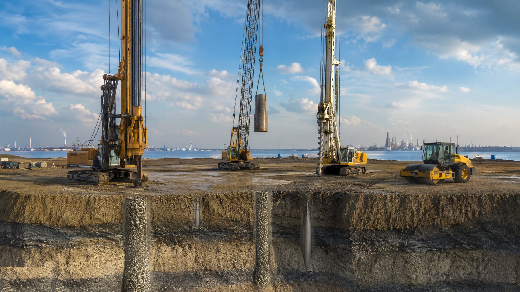
Dynamic compaction is the bluntest tool in ground improvement and one of the most effective. A heavy steel or concrete weight - typically 8-20 tonnes, and up to 40 on the heaviest work - is lifted by a crawler crane and dropped in free fall, commonly from 10-25 m, onto a set-out grid of print positions. Each impact sends a shock wave down through the ground, collapsing the loose structure of the soil and driving the particles into a denser packing. The surface craters - typically by half a metre to two metres - the craters are levelled, and the process is repeated over two to four passes until the ground below has taken the energy the design calls for. There is nothing subtle about it and nothing hidden - you can watch the ground go down.
The method suits loose granular ground with air in it: old made ground, quarry and colliery backfill, demolition rubble fill, loose natural sands and gravels, and reclaimed land placed without compaction. It works because those materials can be shaken into a tighter arrangement. It does not work in soft saturated clays, where the water in the pores cannot escape fast enough for the soil to densify - the energy just kneads the ground and can leave it worse than it started. Water level matters as much as soil type: the ground responds best where the water table sits a couple of metres or more below the impact surface, and where it does not, a granular blanket, a lowered water table or a different method altogether comes first. Depth of treatment follows a long-standing rule of thumb - roughly the square root of the weight in tonnes multiplied by the drop height in metres, scaled by a coefficient generally taken somewhere between 0.4 and 0.6 - which for ordinary plant puts the useful improvement in the top 4-8 m. The treatment depth for a given job is the geotechnical designer's, not the rule of thumb's. A variant, dynamic replacement, punches stone into softer ground to form large columns, but that is a different design problem.
What rules dynamic compaction out is usually not the ground but the neighbours. Every drop puts energy into the ground that travels outwards as vibration, and buildings, buried services, sensitive equipment and people all have limits. Stand-offs are routinely measured in tens of metres rather than the handful people expect, and the distance, the vibration monitoring regime and the trigger levels all come from the geotechnical designer and are agreed before a weight leaves the ground. Beyond that it is a satisfyingly measurable technique: the surface is surveyed before and after - total settlement across a treated area commonly runs to 3-10% of the thickness being improved - crater depth is recorded at every print, and penetration testing before and after shows exactly what the passes achieved. Few ground improvement methods hand you such direct evidence that they worked, and few are as cheap per square metre once the crane is up, which is why it is rarely considered on anything smaller than a few thousand square metres.
How does Dynamic compaction work, step by step?
- 1
Step 1: Establish whether the ground and the setting will take it
The ground investigation has to show loose, compressible material that will respond to impact, and it has to show where the water table sits. At the same time the setting is assessed: distances to buildings, buried services, culverts, mine workings, retaining structures and anything vibration-sensitive nearby. The geotechnical designer sets the treatment depth required, the grid arrangement - primary prints commonly at 5-10 m centres, with later passes on offset grids that halve the effective spacing - the number of passes, usually two to four plus an ironing pass, and the energy applied at each print. If the stand-off the vibration assessment demands leaves too little of the site treatable, the method is simply wrong for the job and a quieter one is chosen.
- 2
Step 2: Protect the neighbours before anything is lifted
Pre-condition surveys are carried out on every structure that could later claim damage, photographed and signed. Vibration monitors go on the boundary at the sensitive receptors, with trigger levels agreed and a named person who receives the alerts. Exclusion zones are set for flying debris as well as for the crane, and on a dry rubble fill they run to tens of metres - always wider than people expect, and always taken from the assessment rather than from the last job. Occupiers are told what is coming and when, because a household that knows the programme complains far less than one that wakes up to it.
- 3
Step 3: Set out the grid and run the first pass
The primary grid is set out and marked. The weight is dropped repeatedly at each print position - typically five to fifteen times, sometimes more - while the crater depth is measured every few drops, and the record is kept print by print. A crane and crew in steady production commonly work through thirty to sixty prints in a shift. The pass stops at a position when the ground stops responding - the crater deepens no further, or the surface around the print begins to heave, which means the energy is going sideways rather than down. Those criteria come from the trial and from the designer, and the crane operator does not decide them.
- 4
Step 4: Level the craters and run the following passes
Craters are backfilled with imported granular material or with the ground heaved up around them, and the surface is levelled ready for the next pass. Subsequent passes go in on offset grids so the untreated ground between the first prints is caught. In water-bearing or fine-grained ground a rest period - anything from a few days to a fortnight - is allowed between passes so that the pore pressures raised by the impacts can dissipate - hitting the same ground again too soon achieves nothing and can soften it. The waiting is part of the design, not slack in the programme.
- 5
Step 5: Finish with a low-energy ironing pass
The heavy passes densify the ground at depth but leave the top loose and churned. A final ironing pass covers the whole surface on a close, overlapping grid with the weight dropped from perhaps a quarter to a third of the main pass height, or with a heavy roller, to compact the upper metre or two that the deep passes disturbed. The area is then regulated to level, proof-rolled and, where it will be trafficked, capped. Skip this and you have a well-compacted mass with a loose crust on top, which is exactly the part a slab or a road will find.
- 6
Step 6: Prove the improvement
Verification compares the ground before and after. Penetration testing is repeated on the baseline lines - typically one profile for every few hundred to a couple of thousand square metres - and sited between prints rather than in the middle of one, so the result reflects the weakest treated ground and not the best. Total surface settlement is surveyed and reconciled with the volume of crater backfill, and plate load testing is carried out where the design calls for it. Results go to the designer against the acceptance criteria, and areas that fall short are given further passes before anything is built on them.
What are the benefits of Dynamic compaction?
- Treats large open areas quickly and cheaply once the crane is set up - a shift commonly covers 500-1,500 m²
- Handles obstruction-rich made ground that would defeat a drilled or bored technique
- Uses no grout, no concrete and no imported stone beyond crater backfill
- The improvement is directly measurable - surface settlement and crater records give evidence as you go
- Reaches usefully deep in the right ground - commonly the top 4-8 m - with no spoil to dispose of
- Plant and crew are simple compared with grouting or mixing operations
What are the limitations of Dynamic compaction?
- Vibration rules it out close to buildings, services and sensitive occupiers - stand-offs in the tens of metres are normal, and stand-off is often the deciding constraint
- Ineffective in soft saturated clays, where the water cannot escape fast enough for the soil to densify
- A water table within a metre or two of the impact surface limits or prevents treatment unless it is lowered or blanketed first
- Very noisy and highly visible - a poor neighbour on any populated site
- Treatment depth is limited by the energy that can be applied - beyond roughly 8-10 m even heavy plant struggles - so deep soft layers need another method
- Leaves a loose, disturbed crust a metre or two thick that has to be re-compacted as a separate operation
What is Dynamic compaction best suited for?
What plant does Dynamic compaction need?
- Crawler crane of 50-100 t with a free-fall winch and a boom rated for the duty - capacity is typically two to three times the pounder weight
- Pounder of 8-20 t, steel or concrete, with its release mechanism and lifting gear, inspected daily
- Dozer and excavator for levelling craters and handling backfill
- Heavy vibrating roller, commonly 15-20 t, for the final ironing and surface regulation
- Vibration monitors with telemetry at the agreed receptor positions
- Survey equipment and a penetration testing rig for before-and-after profiling
How is Dynamic compaction quality-checked?
- Pre-condition surveys of neighbouring structures completed and signed before work starts
- Vibration monitoring against agreed trigger levels, with recorded action when a trigger is passed
- Print-by-print records of drop count and crater depth - five to fifteen drops a print is the usual order - against the design criteria
- Rest periods between passes - days to a fortnight - observed where the design requires them
- Surface level survey before and after, reconciled with the volume of crater backfill - total settlement of 3-10% of the treated thickness is the usual order
- Post-treatment penetration testing sited between prints, compared with the pre-treatment baseline