Jet grouting
Cut the soil apart with a jet and put it back mixed with grout - the technique that works where nothing else fits.
Last updated 2026-08-25
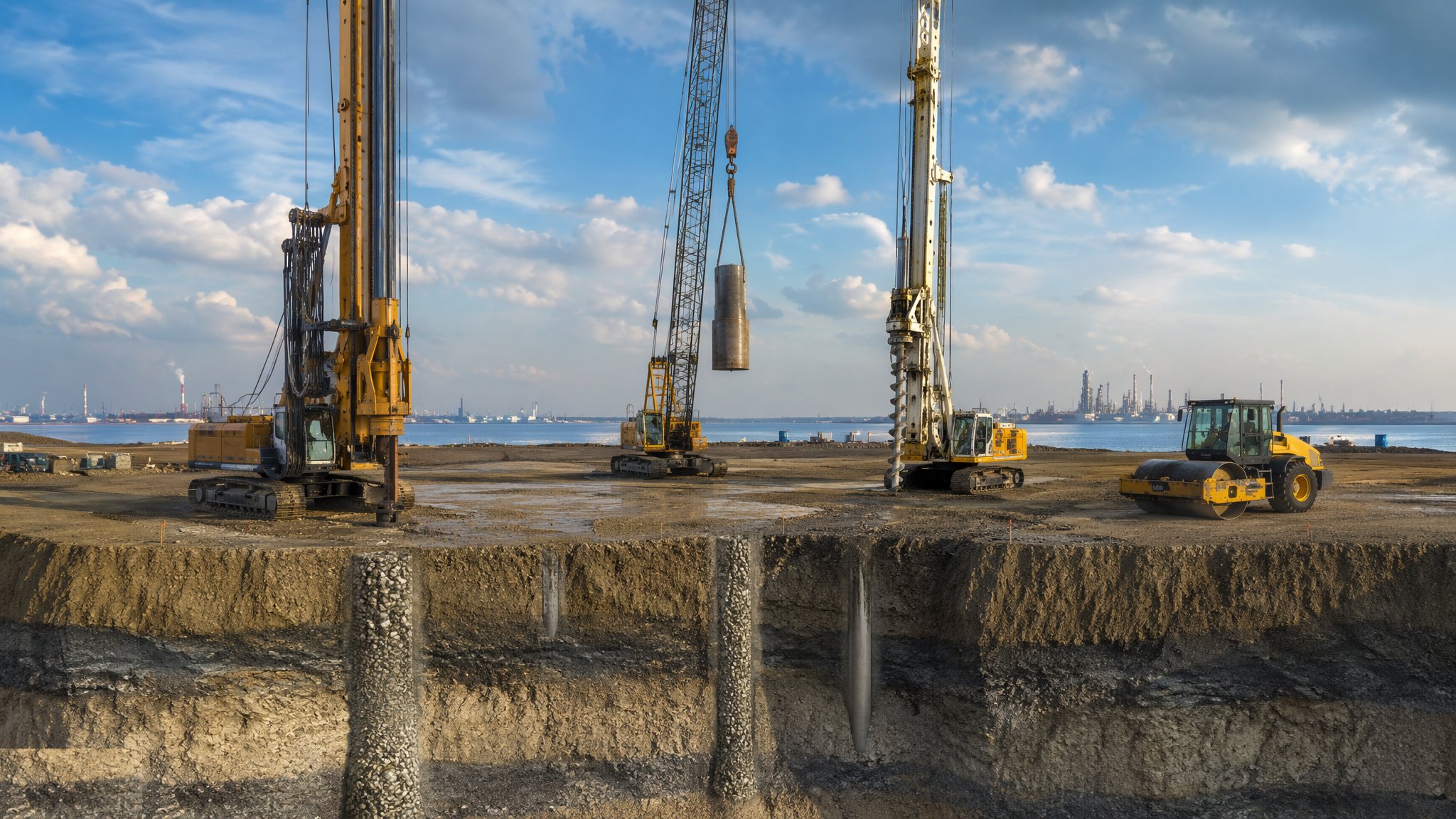
What is Jet grouting?
Jet grouting uses a fluid jet at very high pressure to break the soil apart in place and mix it with cement grout, forming a body of hardened soil-cement in the ground. A slim drill string, boring a hole of only 90-150 mm, is taken down to the design depth, the jet is switched on, and the string is rotated and withdrawn - slowly, at centimetres a minute - cutting a roughly cylindrical column as it rises. Rotate fully and you get a column; rotate through part of a turn and you get a panel; hold the string still and you get a thin wall. Because the cutting is done by the jet rather than by a mechanical tool, the body being formed is many times larger than the hole drilled to reach it - a 100 mm bore routinely produces a column of a metre or more.
Three arrangements are in common use, and the specialist contractor chooses between them on the ground and on the geometry required. The simplest jets grout alone, and typically forms columns of around 0.4-1.2 m depending on the soil. The next surrounds the grout jet with a shroud of compressed air, which lets the jet travel further before it loses its cutting power, and commonly reaches 0.8-1.8 m. The most capable uses a water jet with an air shroud to erode the soil and places the grout separately, which gives the cleanest replacement and the largest bodies - 1.2-3 m is typical, and more in loose sands - but produces by far the most spoil. Coarse granular soils erode easily and give large bodies; stiff and plastic clays resist the jet and give smaller, more variable ones - so the geometry that can actually be achieved is a property of the ground, not a figure picked off a table.
Jet grouting is chosen when nothing else will fit. The rigs are small - a basement machine can be under 2 m wide and work beneath 3 m of headroom - and the drilled hole is slim, so treatment can be placed beneath existing foundations, around live services and between obstructions that would stop a bored or driven technique. Depths of 20-30 m are routine and 50 m is reached where the geometry demands it. Typical work is underpinning ahead of a deep dig, sealing a base plug against water, treating ground around a tunnel eye, or closing the gaps a piled wall cannot reach. The risk that comes with it is heave. The jet puts a large volume of fluid into the ground - the returning spoil can amount to anything from a fifth of the volume being treated to the whole of it - and all of that has to come back up the annulus of the drilled hole. If that return blocks, pressure builds in the ground and lifts whatever is above it - which, given where jet grouting is normally used, is often the very structure being protected.
How does Jet grouting work, step by step?
- 1
Step 1: Survey everything the treatment could reach
Before the design is finished, the buried world around the works is established: services, drains, basements, foundations, culverts and old structures. Jet grouting moves fluid a long way through the ground and it will find any opening - a cracked drain, a service duct, a neighbour's cellar. The geotechnical designer sets the treatment geometry and the specialist contractor sets the jetting parameters, but both are constrained by what is nearby. Monitoring points go on adjacent structures and services before drilling starts, and are read for a week or two beforehand so that the normal seasonal movement of the building is known, giving a baseline worth defending.
- 2
Step 2: Prove the geometry with trial columns
The size and quality of the body a given set of parameters produces in a given soil is uncertain enough that it has to be proved on site. Two or three trial columns per soil horizon are formed and then verified - exhumed where the depth allows, which in practice means the top two or three metres, cored where it does not, or probed by drilling around them to find their edges. The trial confirms whether the design geometry is achievable in this ground and fixes the production parameters. It also shows whether the spoil return behaves as expected, which is the other thing the trial is there to find out.
- 3
Step 3: Drill to depth
A slim string is drilled to the bottom of the treatment zone, usually with a flush to hold the hole and remove cuttings. Position and inclination are set carefully and checked, because deviation compounds with depth: at 25 m, a drift of one percent takes the toe a quarter of a metre off line, two columns designed to overlap will miss each other if both drift that way, and the gap between them is buried and invisible. Where the string passes through material that must not be disturbed, or runs close to a structure, the drilling method and the flush are chosen to suit rather than for speed.
- 4
Step 4: Jet on withdrawal
At depth the jetting fluids are brought up to working pressure - far beyond anything an ordinary grout pump produces, and high enough that the jet would cut a limb as readily as it cuts sand - and the string is rotated, typically a handful of revolutions a minute, and lifted in small steps at a controlled rate measured in centimetres a minute. The controlling parameters - pressure, flow, rotation and lift rate - are those fixed by the trial, and the rig records them continuously against depth. A rig in production commonly forms 50-150 linear metres of column in a shift, which on deep work is only a handful of columns. A column formed with a rig record that shows a pause, a pressure drop or an excursion in lift rate is a column that needs explaining, because the body it produced will not be the body the design assumed.
- 5
Step 5: Watch the spoil return like a hawk
Spoil returning to the surface is the single most important real-time control on a jet grouting job. The volume and consistency are compared against what the trial produced, and a return that stops, thins or thickens noticeably means the fluid being injected is going into the ground instead of coming back - which is the mechanism that lifts buildings. Work stops, the hole is cleared, and the cause is found. Monitoring on adjacent structures runs continuously, read at intervals of minutes rather than days while jetting is under way, with agreed trigger levels, and the response when a trigger is reached is written down and rehearsed rather than improvised in the middle of the night.
- 6
Step 6: Verify the treated body and clean up
Once cured, the treatment is verified against the acceptance criteria: coring through columns and overlaps with strength testing of the recovered material, commonly on something like one column in twenty to one in fifty, checks that adjacent bodies actually intersect where they were meant to, and water testing where the treatment is there to cut off flow. Returned spoil is a cementitious, highly alkaline waste - and on a triple-fluid job there can be as much of it as there is treated ground - so it is contained, settled and disposed of properly - it must never reach a drain or a watercourse. The rig records, the trial results and the verification results together form the file the permanent works designer will rely on.
What are the benefits of Jet grouting?
- Works in almost any soil, from clean sands to clays, where other in-situ methods are ground-specific
- Small rigs - under 2 m wide, working beneath 3 m of headroom - reach into basements and confined spaces no other technique can enter
- Treatment can be placed directly beneath existing foundations, so underpinning is possible without excavating
- The slim drilled hole threads between services and obstructions that would stop a bored or driven method
- Forms columns, panels or walls from the same plant, so complex geometry is achievable
- Produces strength and low permeability in a single operation
What are the limitations of Jet grouting?
- Heave from a blocked spoil return is a real and serious risk, usually exactly where it matters most
- The geometry achieved varies with the ground, differing by a factor of two or more between a clean sand and a stiff clay, and is never fully known without verification
- Grout can travel into services, drains, basements and permeable layers well beyond the treatment zone
- Generates alkaline spoil in volumes of a fifth to the whole of the ground treated, all of which has to be contained, settled and disposed of
- High-pressure fluid systems are hazardous in themselves and demand disciplined exclusion and maintenance
- Expensive for the volume treated - typically several times the rate of a stone column scheme - so it is used where nothing else fits rather than for bulk improvement
What is Jet grouting best suited for?
What plant does Jet grouting need?
- Compact jet grouting rig, from basement machines under 2 m wide to full-size plant, with a mast suited to the headroom available
- High-pressure pumps and, depending on the system, an air compressor and a water pump
- Grout batching, mixing and holding plant - mixes are commonly around one part water to one of cement by weight - with recording of what is produced
- Rig instrumentation logging pressure, flow, rotation and lift rate against depth
- Spoil handling - containment, settlement tanks and tankering for disposal
- Monitoring instrumentation on adjacent structures, with telemetry and alarms
How is Jet grouting quality-checked?
- Buried services and structures surveyed and marked before any drilling
- Trial columns verified for geometry and strength, with production parameters fixed from them
- Drilled position and inclination recorded, with deviation checked wherever overlaps are critical
- Continuous rig records of jetting parameters against depth for every column
- Spoil return observed and logged throughout, with work stopped on any loss of return
- Cores through columns and overlaps, typically one column in twenty to one in fifty, tested at the specified age against the acceptance criteria