Diaphragm walling
A concrete wall cast in a trench held open by fluid - built before the hole exists, and still there when the building is finished.
Last updated 2026-09-05
What is Diaphragm walling?
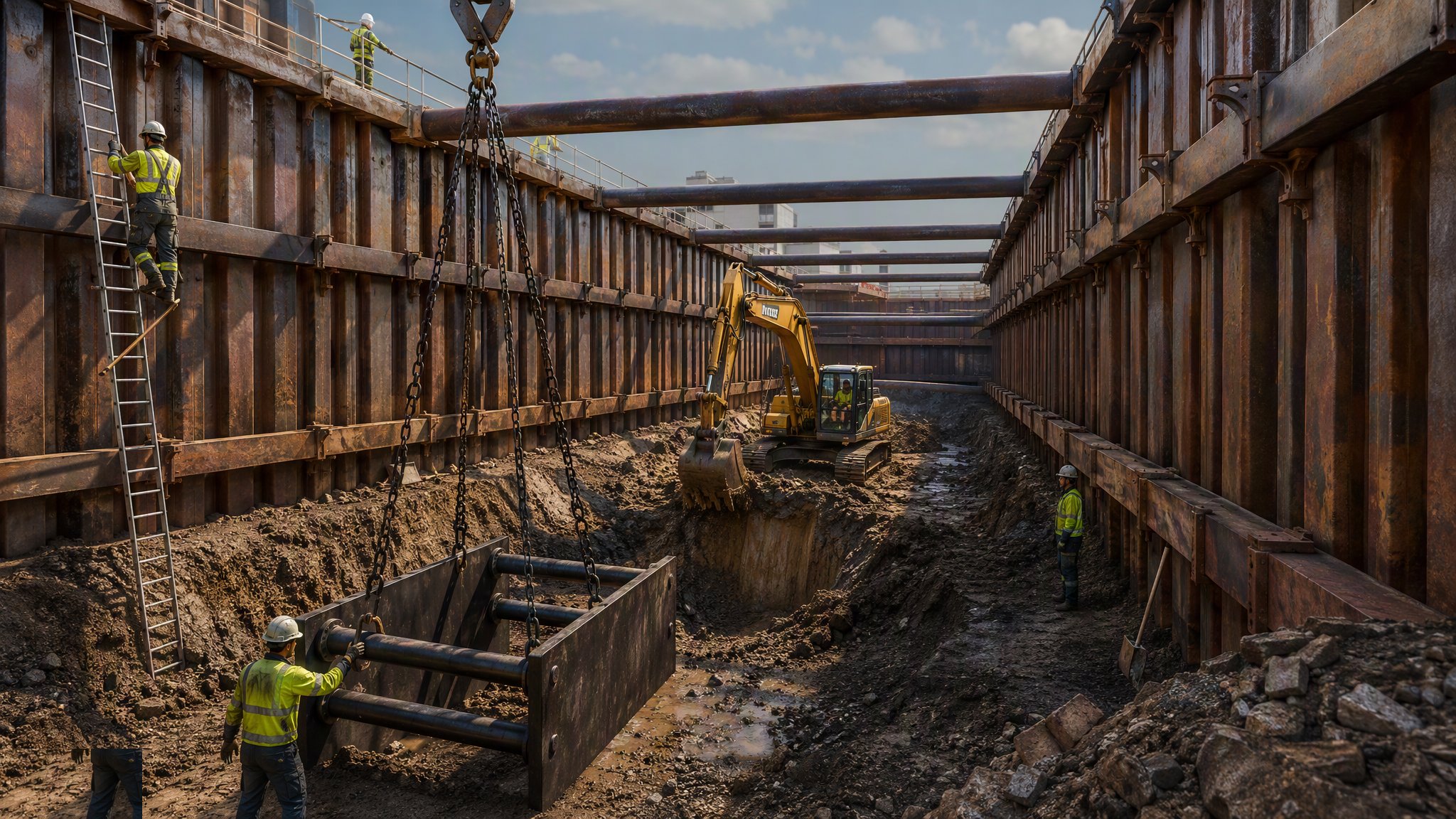
A diaphragm wall is a reinforced concrete wall built in the ground, panel by panel, before any bulk excavation starts. A narrow trench - commonly 600 mm to 1.2 m thick, and 1.5 m or more on the heaviest work - is excavated to full depth and kept open by a support fluid, a reinforcement cage is lowered in, and concrete is placed from the bottom up so that it displaces the fluid rather than mixing with it. Panels are typically 2.5-7 m long on plan, sized as a whole number of grab bites, and they are built in a planned order rather than simply working along the line. Repeat that along the line of the basement and you have a continuous wall that holds the ground back while you dig, and then carries load and keeps water out for the life of the building. That dual role is the point of the technique. You are not building temporary support that gets thrown away - you are building the permanent structure first and excavating inside it afterwards.
It is chosen when the wall has to be deep, stiff, watertight and quiet. Deep, because a fluid-supported trench routinely reaches 20-40 m and, with a cutter, well past 50 m - depths at which most of the alternatives have run out. Stiff, because the ground movement behind the wall is what cracks the terrace next door, and a thick concrete wall propped as you dig moves far less than a driven section. Watertight, because a basement box in the water table has to keep the water on the outside. And quiet, because there is no driving and no vibration, which is often the deciding factor on a city site with old, shallow-founded neighbours. It is the standard answer for deep basements under tall buildings, cut-and-cover tunnels and stations, and any box where the wall has to be permanent.
What makes it expensive is what makes it work. A diaphragm wall job is a fluid-handling operation as much as a concreting operation, with batching, storage, cleaning and disposal plant occupying something like 300-800 m² of compound that a congested site rarely has spare. A grab rig on a crawler base commonly weighs 80-150 tonnes and a cutter rig more, so the working platform - typically 600 mm to 1.2 m of well-graded granular fill - is a designed structure standing alongside an open trench. And the quality is buried the moment it is built - almost every defect on a diaphragm wall is discovered months later when the excavation exposes the face. That is why the discipline sits in the records: the trench survey, the fluid tests, the concrete volume against the theoretical volume. Every dimension, fluid property and panel size comes from the temporary works designer and the specialist contractor, sized to the ground and the loads on that particular site.
How does Diaphragm walling work, step by step?
- 1
Step 1: Fix the design and the panel layout
The wall is designed by the temporary works designer and the permanent works designer together, because it serves both. Ground investigation sets what the trench will stand up in and what the fluid has to do; the retained height, the water table and the loads either side set the wall itself; and the sensitivity of the neighbours sets how much movement is allowed. The line is then split into panels and given a construction order. Panels are commonly 2.5-7 m long - a single grab bite of around 2.5-3 m where the ground is poor or a service is close, three bites where the ground will stand long enough to take them - and primary and secondary panels usually alternate, so each secondary closes against two primaries that are already cast. That panel layout is a real engineering decision, not a drafting exercise - it fixes where every joint falls, and the joints are the weak points of the finished wall.
- 2
Step 2: Build the guide walls
Two short reinforced concrete walls - typically 1-1.5 m deep and 150-300 mm thick, cast slightly wider apart than the nominal panel - are built down each side of the line, and the trench is excavated between them. They do three jobs: they hold the top of the ground open where it is loosest, they retain the fluid above ground level so the pressure inside the trench stays higher than the groundwater outside, and they guide the grab or cutter so the trench starts in the right place. Everything downstream inherits their accuracy. A guide wall built out of line, out of level or too weak to take the cage and stop-end loads puts the fault into every panel that follows it, and there is no correcting it later.
- 3
Step 3: Excavate the panel under support fluid
A hydraulic grab bites out the trench in slices of around 2.5-3 m at a time, or a cutter mills its way down where the ground is hard or the tolerance is tight, with a cutter also feeding back a continuous record of how vertical it is running. Excavating a panel to 20-30 m commonly takes the better part of a shift, and a good deal longer through obstructions or rock. The trench is kept full of support fluid throughout, topped up as fast as spoil comes out. The fluid does not glue anything together - it holds the walls of the trench up by pressure and by sealing the face. Lose the level, hit a permeable seam that swallows fluid, or stop the works with the trench half full, and the trench can collapse. Fluid level is watched continuously, not checked at the end of the shift.
- 4
Step 4: Clean the trench and set the stop ends
Spoil that the grab did not lift settles to the base and dirt loads up in the fluid as the dig goes on. Before concreting, the fluid is circulated through cleaning plant until it is back within the properties the specialist contractor has set, and the base is cleaned of settled material. Skip this and the tremie concrete arrives on top of a bed of soft spoil, and the wall does not sit on what the designer assumed. Stop ends are then lowered down each end of the panel to form the joint against the next panel, and the reinforcement cage - often 10-25 tonnes, and lifted in two sections with a splice made over the trench where the crane or the headroom will not take it in one - is craned in and hung off the guide walls with its cover spacers in place.
- 5
Step 5: Concrete by tremie, bottom up
Concrete is placed down a tremie pipe, typically 200-300 mm in diameter, with its outlet buried in the concrete already placed to a depth the specialist contractor fixes, so fresh concrete rises from the base and pushes the fluid up and out ahead of it. Displaced fluid is recovered for cleaning and re-use. The pipe is shortened as the level rises, and it must never be lifted clear of the concrete - if it is, fluid gets underneath the next charge and leaves a layer of contamination across the panel. The concrete has to flow and self-compact around a dense cage without segregating, so the mix is designed for that. A single panel commonly takes 60-200 m³ in one uninterrupted pour, which means a delivery arriving every 15-20 minutes for most of a shift and a supply chain that has to hold up for all of it. Concrete volume is logged against the theoretical volume as the pour proceeds, because the running total tells you about the shape of a trench nobody can see.
- 6
Step 6: Cap, excavate in stages and expose the wall
Panels are built in a sequence that lets each new one key into the last, the tops are trimmed back to sound concrete and a capping beam ties the line together. Only then does the dig start, taken down in stages - commonly 3-5 m at a time - with props, slabs or anchors installed at each level before the next lift comes out, exactly as the temporary works designer scheduled it. Movement of the wall and the ground behind it is monitored against agreed trigger values as the excavation deepens. As the face is exposed, joints and any local defects are inspected and remedial grouting or facing is agreed with the designer before the internal structure closes them off.
What are the benefits of Diaphragm walling?
- One wall serves as temporary support and permanent structure, saving a separate basement wall inside it
- No driving and no vibration, so it can be built alongside sensitive and shallow-founded neighbours
- Very stiff when propped, which keeps ground movement behind the wall low and protects adjoining property
- Reaches 40 m and beyond, and takes loads that sheet piling and contiguous walling cannot
- Cuts water out effectively, which makes a deep basement in a high water table practical
- Can be built hard against a boundary, recovering site area that a battered excavation would lose
What are the limitations of Diaphragm walling?
- High set-up cost and a plant and fluid compound of several hundred square metres, so it rarely pays below a few hundred metres of wall
- Support fluid has to be batched, stored, cleaned and eventually disposed of as a controlled waste
- Joints between panels are the weak line - most leakage on a finished wall is at a joint, not through a panel
- The trench runs slightly out of plumb over depth, so panels can part company near the base if verticality is not controlled
- Quality is buried until the excavation exposes it, and by then remedial work is on the critical path
- Needs a designed and maintained working platform for heavy, top-loaded plant standing next to an open trench
What is Diaphragm walling best suited for?
What plant does Diaphragm walling need?
- Hydraulic grab on an 80-150 t crawler crane, or a milling cutter rig where the ground is hard or tolerances are tight
- Support fluid batching, storage and cleaning plant, with silos, tanks and pumps
- Service crane for reinforcement cages, tremie pipes and stop ends
- Stop-end sections and the extraction gear that pulls them once the concrete has set
- Tremie pipes of 200-300 mm, hoppers and concrete pumps, with a supply chain able to deliver every 15-20 minutes and keep a pour continuous
- Instrumentation for wall and ground movement, plus survey control for verticality and panel position
How is Diaphragm walling quality-checked?
- Guide walls surveyed for line and level and checked for strength before excavation starts
- Support fluid tested on delivery to the trench and again before concreting, against the specialist contractor's limits
- Trench verticality recorded from the rig and base cleanliness confirmed before the cage goes in
- Cage position, splices and cover spacers checked before lowering, and the hanging level recorded
- Concrete volume logged against theoretical volume through the pour, with over- and under-supply investigated
- Exposed face and joints inspected as the excavation proceeds, with defects recorded and closed out by the designer
More excavation support and trench shoring methods
Next method
Cofferdams